TS8100-PC-PUMP-USER-GUIDE.pdf - 第5页
16 ITEM NO. PART NUMBER DESCRIPTION QTY. 1 7509 ‐ 0070 FLEX, COUPLING 1 2 7509 ‐ 0120 ROTOR,2. 5 PITCH 1 3 7509 ‐ 0100 MOTOR MOUNT PLATE 1 4 7509 ‐ 0140 STATOR HOUS ING …
4
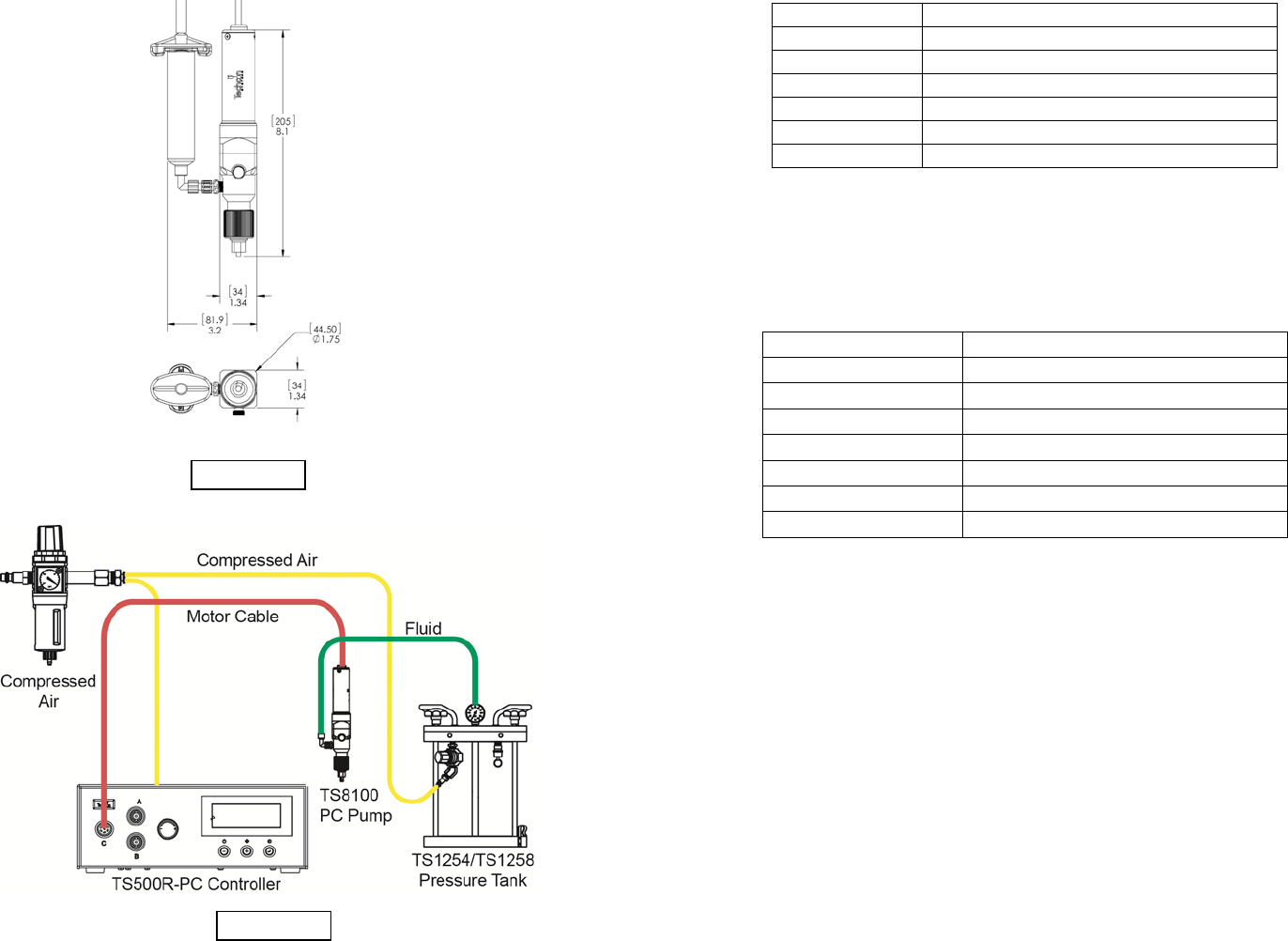
Figure 1.0
Figure 2.0
2. DIMENSIONS AND TYPICAL SETUP
17
9. STANDARD ACCESORIES:
10. OPTIONAL ACCESORIES:
PARTNUMBER DESCRIPTION
8100‐CLEANKIT CLEANINGKIT
8100‐SYBRACKET SYRINGEBRACKETKIT
8100‐MBRACKET MOUNTINGBRACKET
TSD931‐96 FEMALELUERWITH1/8NPTTHREAD
TSD931‐82B MALEADAPTERLUERLOCK,BLACKNYLON
TSD931‐81B ELBOW90°LUERLOCK,BLACK‐NYLON
PART NUMBER DESCRIPTION
TN00DKIT Complete Dispensing Tip Kit
9000-000-112 Sample Tip Kit
7105XCON Conditioning Cream, 10cc
7305XCON Conditioning Cream, 30cc
71003RHB 10cc Receiver Head, 3ft (0.9M)
73003RHB 30cc Receiver Head, 3ft (0.9M)
16
ITEM
NO.
PART
NUMBER
DESCRIPTION QTY.
1 7509‐0070 FLEX,COUPLING 1
2 7509‐0120 ROTOR,2.5PITCH 1
3 7509‐0100 MOTORMOUNTPLATE 1
4 7509‐0140 STATORHOUSING 1
5 2800‐0836SETSCREW,M2.5X3MMLG, 1
6 2800‐0903 M3X6SSSETSCREW 1
7 7509‐0160 STATOR 1
8 3300‐0586 SEAL 1
9 3300‐0595 DOWELPIN1.5X5MM 1
10 2800‐0901 M3X6MMFLATHEADPHILIP 3
11 2800‐0897 M2.5X14MMSHCSCREW 4
12 2800‐0898 WASHER,SEAL 1
13 2800‐0899 THUMBSCREW 1
14 2600‐0185 MOTOR 1
15 7509‐0340 MOTOR,COVER 1
16 7509‐9110 CABLEASSY,SERIES100PCPUMP 1
17 2800‐0900 #4x1/4FLTHDSCREW 3
21 2800‐0917 WASHER#4 4
22 2800‐0295 WASHER,M2.5LOCK,MEDIUM,SS 4
23 7509‐0090 LOCKNUT 1
24 7509‐0130 STATORCAPBOTTOM 1
25 7090‐0030 NEEDLELOCKINGCAP 1
5
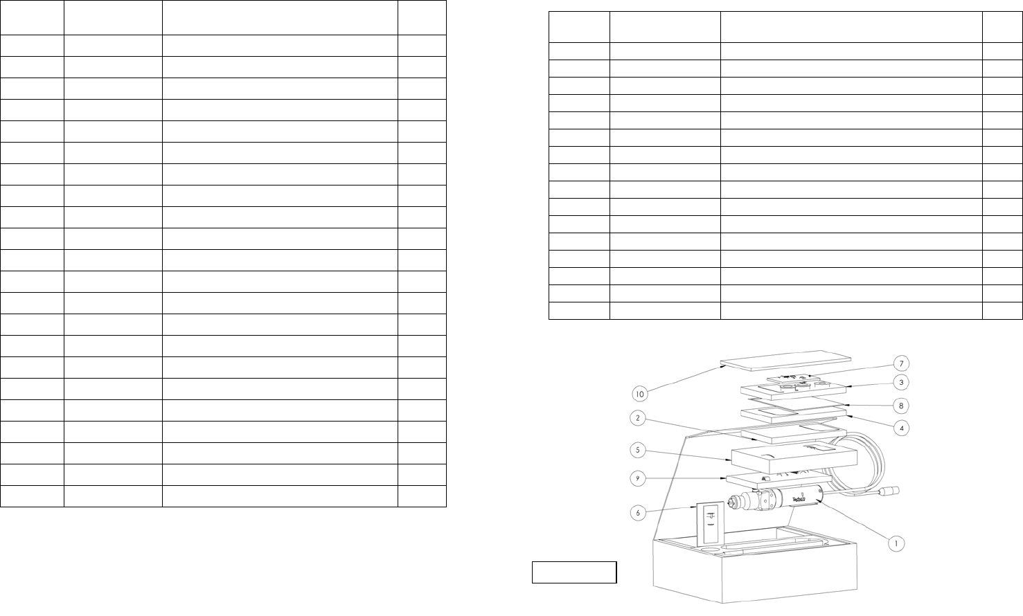
Figure 3.0
3. UNPACKING AND INSPECTION
Carefully unpack the pump and examine the items contained in the carton.
ITEM
NO.
PARTNUMBER DESCRIPTION QTY.
1 7509‐9030 PCPUMP(withoutStator) 1
2 8100‐CLEANKIT Cleaningkit 1
3 8100‐SYBRACKET SYRINGEBRACKETKIT 1
4 8100‐MBRACKET MOUNTINGBRACKET 1
5 A0100488‐2 700SERIES,30ccRECEIVERHEAD 1
6 8100‐100‐002 STATOR 1
7 N/A FITTINGKIT:Includes3fittingsbelow 1
TSD931‐96 FEMALELUERWITH1/8NPTTHREAD 1
TSD931‐82B MALEADAPTERLUERLOCK,BLACKNYLON 1
TSD931‐81B ELBOW90°LUERLOCK,BLACK‐NYLON 1
8 9000‐000‐100 SAMPLENEEDLEKITFORVALVES 1
9 N/A CAP/NUTKIT:Includes3nutandcapsbelow 1
7509‐0090 RETAINERNUT 1
7509‐0130 STATORCAPBOTTOM 1
7090‐0030 NEEDLECAP 1
10 INSTRUCTIONPACKET
Inspect the unit for any damaged which may have occurred in transit. If such damage has
occurred, notify the carrier at once. Claim for damage must be made by the consignee to
the carrier, and should be reported to the manufacturer.
6
Figure 4.0
4. DESCRIPTION
The TS8100 series Positive Displacement Pump is a continuously volumetric dispense
pump based on the Progressive Cavity (PC) technology. The pump is designed to
dispense a wide range of fluids, from low viscosity coatings to high viscosity greases.
The many advantages of PC technology will simplify your dispense process and
improve reliability and quality in the long run.
The TS8100 series PC pump provides a consistent dispensing output due to a special
design of seal cavities in the fluid chamber which created a volumetric fluid flow. Two
main components are the stator and rotor. The metal rotor seals tightly against the
flexible rubber stator as it rotates, forming tightly sealed cavities which move toward
to the pump outlet, carrying the fluid. The pumped fluid does not change in shape or
size during the dispense process. Accuracy and repeatability rate of +/- 1% is
achievable.
5. THEORY OF OPERATION
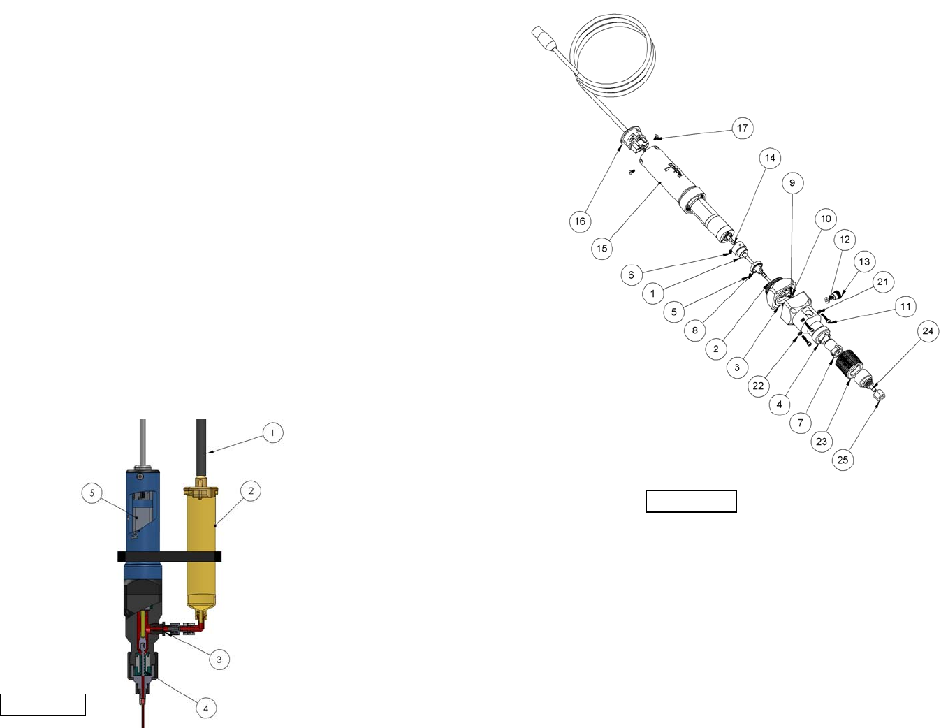
The TS8100 Series Positive Displacement pump dispenses fluid with a positive
displacement action using a progressive cavity technology. Fluid is held in a feed
reservoir (2) under a positive head of air pressure, up to 30 psi (2.07bar), depending
upon the viscosity of the fluid. This positive air pressure, supplied by the air line (1),
forces the fluid out of the barrel (2) into the fluid feed path (3) then to the rotor/stator
chamber assembly (4). Fluid flows from this point (4) to the dispense tip outlet and is
controlled by the rotor rotation in the feed direction. The rotor is driven by the encoder
DC motor (5). Applying a voltage signal to the motor (5), will rotate the rotor and the
fluid will be forced out the dispense tip. The actual fluid deposited is dependent upon
adhesion of the dispensed fluid to the substrate. Shearing of the fluid is achieved by
reverse Z-motion (tip retraction). When the motor stops, the unit remains in position
for a fraction of a second (dwell) to allow the last drop of fluid to flow out of the
dispense tip. After the dwell period, the automation equipment moves the pump to the
next position.
15
8. SPARE PARTS:
Figure 15.0