RTM系列气缸数据表.pdf - 第10页
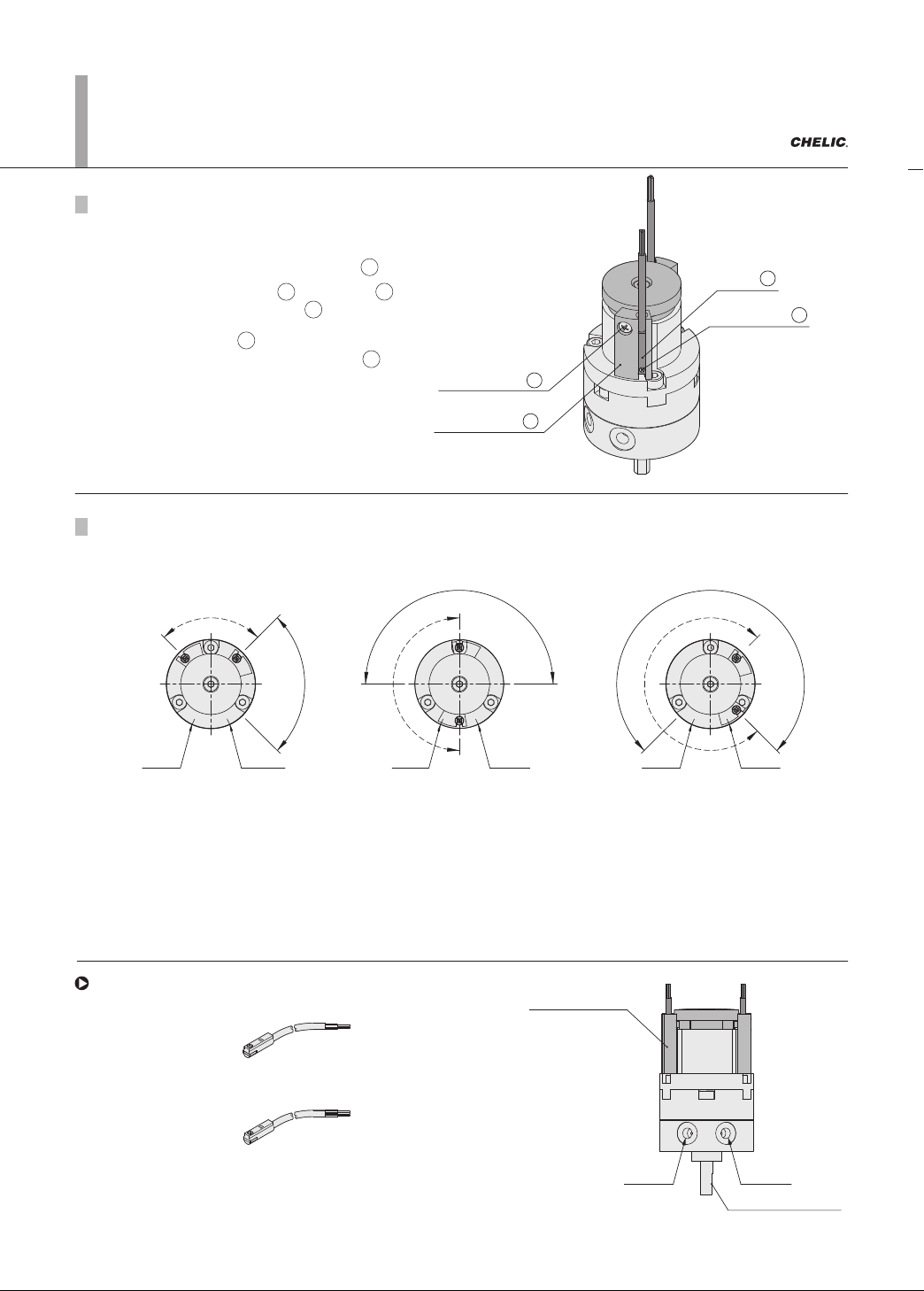
6-12.20 Sensor switch introduction 90° B port A port 180° B port A port 270° B port A port S K Voltage : DC 5V ~ 30V AC 5V ~ 30V Brown (+) Blue ( ) CS-8G CS-8GN(P) Brown (+) Black Blue ( ) Voltage : DC 4.5V ~ 28V Sensor …
6-12.19
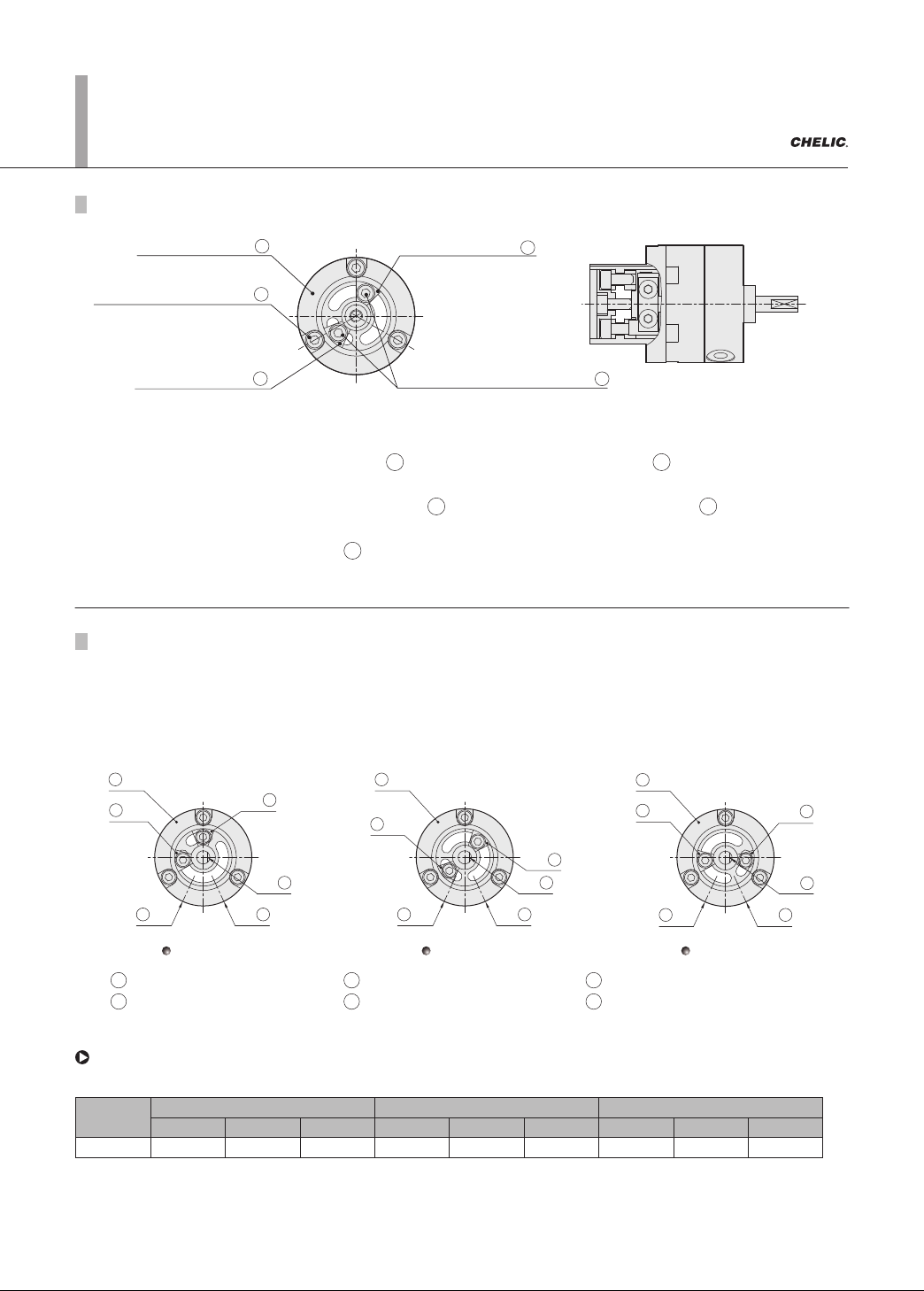
Adjustment method of rotation angle
Sensing position base
M
Fixed screw of Sensing position
N
Angle positioning block
K
Angle positioning block
K
Fixed screw of Angle positioning block
P
Position- A
1
2
3
5
4
6
Position- B
1
2
3
5
4
6
Position- C
1
2
3
5
4
6
1 Sensor positioning base 2 Angle positioning block-1 3 Angle positioning block-2
4 Chamfer 5 A port 6 B port
RTM series Rotary Actuators (Small)
Adjustment
1. Loosen "the fixed screw of sensor holder ", Adjust the "sensor positioning base " to desire setting
position (A, B, C) and then tighten to the fixed screw.
2. Loosen Fixed screw of "Angle positioning block " to allow the" Angle positioning block " sliding on the slot
(Please never loosen completely).
3. Slide the "Angle positioning block " to desire angle and then tighten fixed screw.
4. Match the rotating shaft in order to achieve more accurate positioning.
Method of adjustment :
N M
P K
K
Description of adjustment
There are three angle setting position (as shown in figure - A, B and C below) for sensor positioning base of each
model.
The preset range of adjustment is between internal angle position block inside the cylinder. Since there is a
limitation
of accuracy of the internal angle positioning blocks inside the cylinder, if 90°and 180° accuratepositioning
is required,
please adjust to 270°.
Model
Position - A Position - B Position - C
90° 180° 270° 90° 180° 270° 90° 180° 270°
RTM 0° ~ 90° 130° ~ 180° 175° ~ 225° 30° ~ 90° 0° ~ 180° 0° ~ 250° 0° ~ 10° 105° ~ 180° 105° ~ 270°
While using one group of angel positioning block and fixed to long slot side, the
range of adjustable angle for each specification and listed as below:
Note: 1. Home points are base on clockwise rotated shaft until contacting internal angle positioning blocks serving are 0° . The rotation range is the area
while rotating and contact the angle position blocks again.
2. Specification of 90° is fixed by model A.
6-12.20
Sensor switch introduction
90°
B port A port
180°
B port A port
270°
B port A port
S
K
Voltage : DC 5V ~ 30V
AC 5V ~ 30V
Brown
(+)
Blue
( )
CS-8G
CS-8GN(P)
Brown
(+)
Black
Blue
( )
Voltage : DC 4.5V ~ 28V
Sensor bracket
A port
B port
Shaft cutting face
RTM series Rotary Actuators (Small)
RTP
RTU
RTZB
RTM
RTH
RTBM
RMF
RTB
Sensor switch operating range and the setting
Sensor
S
Sensor fixing
screw holder
K
Sensor fixture
fixing screw
P
Sensor holder
M
P
S
M
K
M
P
Method of adjustment :
1.
Loosen the Fixed screw of the holder " to allow sliding both sides.
2. Insert the sensor switch into Holder to flush with bottom, and
then tighten the fixed screw
.
3. Adjust the Holder to desired angle, and then
tighten the Fixed screw of the holder .
Adjustment method of sensor switch position
Sensor switch position and adjustment method
Description of adjustment:
1.
As illustrated in the above figure, the solid line area indicate rotation area of shaft chamfer, dotted
line indicate rotation area of magnet.
2. The rotation area of magnet represents valid adjustment range of the sensor fixing holder.
The sensor switch is effective within this range.
Sensor switch introduction
Brown (+)
Blue (‒)
DC 5 ~ 120V
AC 5 ~ 120V
Voltage:
CS-9D
Brown (+)
Blue (‒)
DC 5 ~ 120V
AC 5 ~ 120V
Voltage:
CS-9B
Brown (+)
Blue (‒)
DC 5 ~ 30V
Voltage:
CS-8B
Brown (+)
Blue (‒)
DC 5 ~ 120V
AC 5 ~ 120V
Voltage:
CS-15B
DC 5 ~ 120V
AC 5 ~ 120V
Voltage:
CS-95
Brown (+)
Blue (‒)
DC 5 ~ 120V
AC 5 ~ 120V
Voltage:
CS-30E
DC 5 ~ 120V
AC 5 ~ 120V
Voltage:
CS-100
Brown (+)
Blue (‒)
DC 5 ~ 120V
AC 5 ~ 120V
Voltage:
CS-15T
DC 5 ~ 30V
Voltage:
CS-15TN(P)
Brown (+)
Black
Blue (‒)
CS-15TN
Brown (+)
Blue (‒)
DC 5 ~ 120V
AC 5 ~ 120V
Voltage:
CS-6T
Brown (+)
Blue (‒)
Brown (+)
Blue (‒)
DC 5 ~ 30V
Voltage:
CS-8G
Brown (+)
Blue (‒)
DC 5 ~ 30V
Voltage:
CS-7B
Brown (+)
Black
Blue (‒)
DC 4.5 ~ 28V
Voltage:
CS-8GN(P)
Brown (+)
Blue (‒)
DC 5 ~ 30V
Voltage:
CS-30EN(P)
DC 10 ~ 28V
Voltage:
CS-180
Brown (+)
Blue (‒)
Brown (+)
Blue (‒)
DC 10 ~ 28V
Voltage:
CS-181
Brown (+)
Blue (‒)
Brown (+)
Blue (‒)
DC 5 ~ 120V
AC 5 ~ 120V
Voltage:
CS-9H
Brown (+)
Blue (‒)
DC 5 ~ 30V
Voltage:
CS-5G
Brown (+)
Black
Blue (‒)
DC 5 ~ 30V
Voltage:
CS-9DN(P)
DC 4.5~28V
Voltage:
CS-5GN(P)
Brown (+)
Black
Blue (‒)
Brown (+)
Blue (‒)
DC 5 ~ 120V
AC 5 ~ 120V
Voltage:
CS-9D
Brown (+)
Blue (‒)
DC 5 ~ 120V
AC 5 ~ 120V
Voltage:
CS-9B
Brown (+)
Blue (‒)
DC 5 ~ 30V
Voltage:
CS-8B
Brown (+)
Blue (‒)
DC 5 ~ 120V
AC 5 ~ 120V
Voltage:
CS-15B
DC 5 ~ 120V
AC 5 ~ 120V
Voltage:
CS-95
Brown (+)
Blue (‒)
DC 5 ~ 120V
AC 5 ~ 120V
Voltage:
CS-30E
DC 5 ~ 120V
AC 5 ~ 120V
Voltage:
CS-100
Brown (+)
Blue (‒)
DC 5 ~ 120V
AC 5 ~ 120V
Voltage:
CS-15T
DC 5 ~ 30V
Voltage:
CS-15TN(P)
Brown (+)
Black
Blue (‒)
CS-15TN
Brown (+)
Blue (‒)
DC 5 ~ 120V
AC 5 ~ 120V
Voltage:
CS-6T
Brown (+)
Blue (‒)
Brown (+)
Blue (‒)
DC 5 ~ 30V
Voltage:
CS-8G
Brown (+)
Blue (‒)
DC 5 ~ 30V
Voltage:
CS-7B
Brown (+)
Black
Blue (‒)
DC 4.5 ~ 28V
Voltage:
CS-8GN(P)
Brown (+)
Blue (‒)
DC 5 ~ 30V
Voltage:
CS-30EN(P)
DC 10 ~ 28V
Voltage:
CS-180
Brown (+)
Blue (‒)
Brown (+)
Blue (‒)
DC 10 ~ 28V
Voltage:
CS-181
Brown (+)
Blue (‒)
Brown (+)
Blue (‒)
DC 5 ~ 120V
AC 5 ~ 120V
Voltage:
CS-9H
Brown (+)
Blue (‒)
DC 5 ~ 30V
Voltage:
CS-5G
Brown (+)
Black
Blue (‒)
DC 5 ~ 30V
Voltage:
CS-9DN(P)
DC 4.5~28V
Voltage:
CS-5GN(P)
Brown (+)
Black
Blue (‒)
6-12.21
90, 180, 270
PT 1/8 PT 1/4
1.5~7(150~700)
0~50
18 35
5 10
0.39 0.60.082 0.12
RTM63RTM50 RTM100RTM80
Ø12 Ø15 Ø25
Ø17
Specification
Rotation angle
Double acting
Air
Internal structure
Cutting
A port B port
S
w
i
n
g
r
a
n
g
e
o
f
c
u
t
t
i
n
g
o
n
s
i
n
g
l
e
1
8
0
°
180°
Cutting
A port B port
S
w
i
n
g
r
a
n
g
e
o
f
c
u
t
t
i
n
g
o
n
s
i
n
g
l
e
2
7
0
°
270°
Code of order
270 270°
—
180 180°
—
90 90°
—
RTM 50 180
Model Torque force Rotation Angle
50 N m: 5
63 N m: 10
80 N m: 18
100 N m: 35
90°
S
w
i
n
g
r
a
n
g
e
o
f
c
u
t
t
i
n
g
o
n
s
i
n
g
l
e
9
0
°
Cutting
A port B port
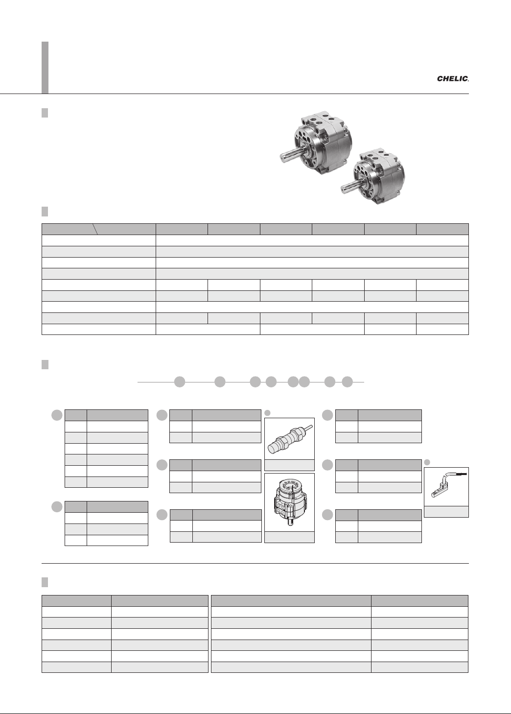
RTM series
Rotary cylinder
RTM 50, 63, 80, 100 Rotary Actuator
Product features
N.m
mm
Torque force
Rotation angle
Pressure range
Ambient and fluid temperature
Allowable kinetic energy
℃
°
J
Kgf/cm² (kPa)
Action
Fluid
Bore size
Port size
Item Model
● Magnetic induction.
● Max. torque up to 113 N˙m
● Three rotation angles: 90° , 180° , 270° .
Feature
RTM series Rotary Actuators
(Large)
Product features, Code of order
Specification
Item Model RTM 50 RTM 63 RTM 80 RTM 100 RTM 125 RTM 150
Fluid Air
Pressure range
(kgf / cm² (kPa))
1.5 ~ 7 ( 150 ~ 700 )
Ambient and fluid temperature
(° C)
0 ~ 50
Action Double acting
Torque force
(N˙m)
5 10 18 35 60 113
Bore size
(mm)
Ø12 Ø15 Ø17 Ø25 Ø30 Ø40
Rotation angle 90° , 180° , 270°
Allowable kinetic energy
(J)
0.082 0.12 0.39 0.6 1.03 1.94
Port size PT 1/8 PT 1/4 PT 3/8 PT 1/2
Code of order
RTM 50 × 180 ‒ LA 1 ‒ C 1 ‒ 8B 1
321 4 5 6 7 8
Mark Torque force
(N˙m)
50 5
63 10
80 18
100 35
125 60
150 113
1
Mark Rotation angle
90 90°
180 180°
270 270°
2
Shock absorber
Sensor bracket
CS-8B
Image
Image
Mark Shock absorber
q�ty
1 1 Pc
2 2 Pcs
Mark Sensor bracket
None
Without sensor bracket
C With sensor bracket
Mark Sensor switch
None
Without sensor switch
8B CS-8B
Mark Sensor bracket
q�ty
1 1 Pc
2 2 Pcs
Mark Sensor quantity
1 1 Pc
2 2 Pcs
Mark Shock absorber
None
Without Shock absorber
LA Shock absorber
4
5
7
6
8
3
6
5
7
8
2
4
10
9
1
3
11
Internal structure
Components and Material list
Rotation angle
90°
Cutting
A port B port
S
w
i
n
g
r
a
n
g
e
o
f
c
u
t
t
i
n
g
o
n
s
i
n
g
l
e
9
0
°
180°
Cutting
A port B port
S
w
i
n
g
r
a
n
g
e
o
f
c
u
t
t
i
n
g
o
n
s
i
n
g
l
e
1
8
0
°
270°
Cutting
A port B port
S
w
i
n
g
r
a
n
g
e
o
f
c
u
t
t
i
n
g
o
n
s
i
n
g
l
e
1
8
0
°
Code of order
CS-8B
SG 2
LA 2
Model
Torque force
Rotation angle
Sensor bracket
Sensor switchShock absorber
LA 1 SB 1C 118050RTM
90 90°-
180 180°-
270 270°-
RTM series
Rotary cylinder
None: Standard
1 = 1 pcs
2 = 2 pcs
Sensor bracket markC
:
Number of
Sensor bracket
2
:
sensor switch code
( CS-8B )
SB
1 = 1 pcs
2 = 2 pcs
Number of
sensor switch
2
:
:
:
2 Number of
shock absorber
1 = 1 pcs
2 = 2 pcs
C 2
50 N m: 5
63 N m: 10
80 N m: 18
100 N m: 35
07
08
09
10
11
01
02
03
04
05
06
Shock absorber
Rocking arm Magnet Rare earth metalsStainless steel
Sensor base
Sensor switchAluminum alloy
Rocking arm base Sensor switch base Aluminum alloyStainless steel
Arm screw Alloy steel Rear cover Aluminum alloy
Angle adjustment base Aluminum alloy Magnet base Aluminum alloy
No. Item Material No. Item Material
RTM 50, 63, 80, 100 Rotary Actuator (Angle adjustment, Sensor switch)
RTP
RTU
RTZB
RTM
RTH
RTBM
RMF
RTB
Product features
Product weight
註 : 以上皆為理論數據;重量
誤差約 ±5%
Model Weight
(kg)
Model Weight
(kg)
RTM 50 0.76 RTM 50 × □ - LA 2 - C 2 1.1
RTM 63 1.29 RTM 63 × □ - LA 2 - C 2 1.5
RTM 80 1.92 RTM 50 × □ - LA 2 - C 2 2.3
RTM 100 3.56 RTM 100 × □ - LA 2 - C 2 3.9
RTM 125 8.56 RTM 125 × □ - LA 2 - C 2 8.9
RTM 150 12.36 RTM 150 × □ - LA 2 - C 2 12.7
Note: All of above are theoretical data. Weight tolerance about±5%
感應器固定座 CS-8G CS-8B CS-9D
CS-9G
CS-9B
CS-15B CS-15TNS-8 CS-7B CS-100CS-30E
CS-5G CS-5GN(P)
CS-8GN(P)
CS-180
CS-65
CS-95 CS-9H
CS-9DN(P)
CS-15TN
CS-15TN(P) CS-6T(H)
Please refer to P.8-2.7