RTM系列气缸数据表.pdf - 第8页
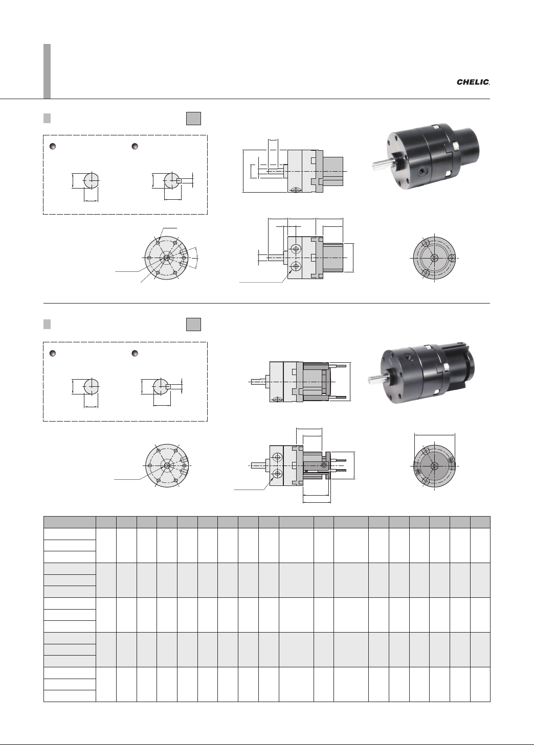
6-12.18 (Port connection) 2-J E G B I M N ØC K A ØO ØS F ØD H 2-T 2-L 2-U 2-U Chamfer ØC ØD E G I B N M H F ØR Q P ØO ØR 2-L 2-T (Port connection) 2-J 2-U 2-U K A Chamfer H ØC ØC 4 1 1.5 H ØC ØC 4 1 1.5 RTM10-90° RTM10-1…
6-12.17
L
ØK
ØK
4
11.5
L
ØK
ØI
M
ØI
N
2-O
RTM10-90°
RTM10-180°
RTM10-270°
RTM15-90°
RTM15-180°
RTM15-270°
A
31
36
B
22
25.7
C
13.3
15.5
D
30
35
E
14
18
F
8
9
G
9
10
H
5
6
I
9
12
J
1
1.5
K
4
5
L
3.5
4.5
M
17
21
N
3
3
O
3.5
3.5
P
10.5
10.5
Q
9.2
10.5
R
M5x0.8p
M5x0.8p
S
25
29
T
3.5
3.5
U
M3x0.5p
M3x0.5p
V
24
29
W
1
1.5
RTM20-90°
RTM20-180°
RTM20-270°
RTM30-90°
RTM30-180°
RTM30-270°
RTM40-90°
RTM40-180°
RTM40-270°
44
52
33.6
47.5
19
27.2
44
51
20
22 13
1010
12
7
8
14
16
1.6
2
6
8
5.5
7.5
26
29
4
4.5
4.2
5.5
15
13.5
13
18.5
M5x0.8p
M5x0.8p
36
42
4.5
5.5
M4x0.7p
M5x0.8p
36
43
1
2
64 53 30.4 64 30 2215 9 25 4.5 10 9 38 5 5.5 19 14 M5x0.8p 52 5.5 M5x0.8p 56 3
A
S
2-U
2-T
Chamfer
RTM10-F RTM15-F RTM20-F RTM30-F RTM40-F
41g 70g 138g 268g 438g
RTM - F 10, 15, 20, 30, 40
N
F
B
H
E
G
P
L
ØD
J
2-O
ØK
C
Q
W
M
(Port connection)2-R
Model
Dimension
Weight
Model
Weight
RTM series Rotary Actuator
Dimensions
RTMF 10 ~ 30
Long shaft side
RTMF 40
Long shaft side
RTMF 10 ~ 40
Short shaft side
6-L
F
H
ØA
ØD
E
G
I
B
N
M
ØK
25°
ØC
25°
ØO
ØR
M
N
Q
P
ØR
ØO
H
ØC
ØC
4
11.5
H
ØC
ØC
4
11.5
RTM10-90°
RTM10-180°
RTM10-270°
RTM15-90°
RTM15-180°
RTM15-270°
A
30
35
B
17
20.1
C
4
5
D
9
12
E
3
4
F
9
10
G
14
18
H
3.5
4.5
I
4.2
5
J
M5x0.8p
M5x0.8p
K
24
29
L
M3x0.5p
M3x0.5p
M
24
28
N
18
22
O
18
24
P
23.3
27.3
Q
24
29.5
R
29
34
RTM20-90°
RTM20-180°
RTM20-270°
RTM30-90°
RTM30-180°
RTM30-270°
RTM40-90°
RTM40-180°
RTM40-270°
44
51
29.1
40
6
8
14
16
4.5
5
10
12
20.3
22
5.5
7.5
8.5
11
M5x0.8p
M5x0.8p
36
43
M4x0.7p
M5x0.8p
28.5
32.5
21
24
30
34
28
30.8
30.5
34
42
47
64 45 10 25 6.5 22 30 9 9.5 M5x0.8p 56 M5x0.8p 34.5 26 34 33 36 47
RTM 10 RTM 15 RTM 20 RTM 30
78g 116g 240g 390g
RTM 40
604g
2-J (supply port)
2-J (P port)
Chamfer
Chamfer
Dimension
Model
Weight
Model
Weight
RTM series Rotary Actuator (Angle adjustment, Sensor switch)
Dimensions
RTM 10 ~ 30
Long shaft type
RTM 40
Long shaft type
RTM10~30
Long shaft type
RTM40
Long shaft type
Model A B C D E F G H I J K L M N O P Q R
RTM 10-90°
30 17 4 9 3 9 14 3.5 4.2 M5x0.8p 24 M3x0.5p 24 18 18 23.3 24 29RTM 10-180°
RTM 10-270°
RTM 15-90°
35 20.1 5 12 4 10 18 4.5 5 M5x0.8p 29 M3x0.5p 28 22 24 27.3 29.5 34RTM 15-180°
RTM 15-270°
RTM 20-90°
44 29.1 6 14 4.5 10 20.3 5.5 8.5 M5x0.8p 36 M4x0.7p 28.5 21 30 28 30.5 42RTM 20-180°
RTM 20-270°
RTM 30-90°
51 40 8 16 5 12 22 7.5 11 M5x0.8p 43 M5x0.8p 32.5 24 34 30.8 34 47RTM 30-180°
RTM 30-270°
RTM 40-90°
64 45 10 25 6.5 22 30 9 9.5 M5x0.8p 56 M5x0.8p 34.5 26 34 33 36 47RTM 40-180°
RTM 40-270°
Unit: mm
RTM series Rotary Actuators
(Small)
Dimensions/ Standard
RTM 10, 15, 20, 30, 40 - L Adjustable angle
RTM 10, 15, 20, 30, 40 - C Sensor bracket
6-12.18
(Port connection)
2-J
E
G B
I
M
N
ØC
K
A
ØO
ØS
F
ØD
H
2-T
2-L
2-U
2-U
Chamfer
ØC
ØD
E
G
I
B
N
M
H
F
ØR
Q
P
ØO
ØR
2-L
2-T
(Port connection)
2-J
2-U
2-U
K
A
Chamfer
H
ØC
ØC
4
11.5
H
ØC
ØC
4
11.5
RTM10-90°
RTM10-180°
RTM10-270°
RTM15-90°
RTM15-180°
RTM15-270°
A
B
C
D
E
F
G
H
I
J
K
L
M
N
O
P
Q
R
S
T
U
RTM20-90°
RTM20-180°
RTM20-270°
RTM30-90°
RTM30-180°
RTM30-270°
RTM40-90°
RTM40-180°
RTM40-270°
RTM10-F RTM15-F RTM20-F RTM30-F
91g 138g 266g 468g
RTM40-F
700g
Dimension
Model
Weight
Model
Weight
RTM-F series Rotary Actuator (Angle adjustment, Sensor switch)
RTP
RTU
RTZB
RTM
RTH
RTBM
RMF
RTB
Dimensions
RTM 10 ~ 30
Long shaft type
RTM 40
Long shaft type
RTM 10 ~ 30
Long shaft type
RTM 40
Long shaft type
Model A B C D E F G H I J K L M N O P Q R S T U
RTMF 10-90°
31 22 4 9 1 9 14 3.5 9.2 M5x0.8p 25 M3x0.5p 24 18 18 23.3 24 29 30 3.5 3.5RTMF 10-180°
RTMF 10-270°
RTMF 15-90°
36 25.7 5 12 1.5 10 18 4.5 10.5 M5x0.8p 29 M3x0.5p 28 22 24 27.3 29.5 34 35 3.5 3.5RTMF 15-180°
RTMF 15-270°
RTMF 20-90°
44 33.6 6 14 1 10 20 5.5 13 M5x0.8p 36 M4x0.7p 28.5 21 30 28 30.5 42 44 4.5 4.2RTMF 20-180°
RTMF 20-270°
RTMF 30-90°
52 47.5 8 16 2 12 22 7.5 18.5 M5x0.8p 42 M5x0.8p 32.5 24 34 30.8 34 47 51 5.5 5.5RTMF 30-180°
RTMF 30-270°
RTMF 40-90°
64 53 10 25 3 22 30 9 14 M5x0.8p 52 M5x0.8p 34.5 26 34 33 36 47 64 5.5 5.5RTMF 40-180°
RTMF 40-270°
Unit: mm
RTM series Rotary Actuators
(Small)
Dimensions/ Flange type
RTMF 10, 15, 20, 30, 40 - L Adjustable angle
RTMF 10, 15, 20, 30, 40 - C Sensor bracket
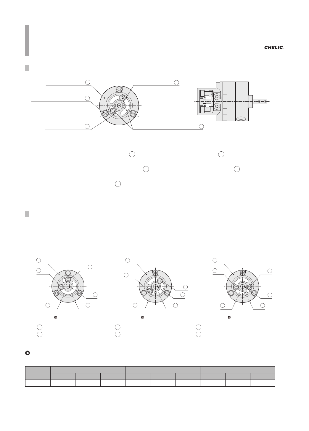
Adjustment method of rotation angle
Sensing position base
M
Fixed screw of Sensing position
N
Angle positioning block
K
Angle positioning block
K
Fixed screw of Angle positioning block
P
Position- A
1
2
3
5
4
6
Position- B
1
2
3
5
4
6
Position- C
1
2
3
5
4
6
1 Sensor positioning base 2 Angle positioning block-1 3 Angle positioning block-2
4 Chamfer 5 A port 6 B port
RTM series Rotary Actuators (Small)
Adjustment
1. Loosen "the fixed screw of sensor holder ", Adjust the "sensor positioning base " to desire setting
position (A, B, C) and then tighten to the fixed screw.
2. Loosen Fixed screw of "Angle positioning block " to allow the" Angle positioning block " sliding on the slot
(Please never loosen completely).
3. Slide the "Angle positioning block " to desire angle and then tighten fixed screw.
4. Match the rotating shaft in order to achieve more accurate positioning.
Method of adjustment :
N M
P K
K
Description of adjustment
There are three angle setting position (as shown in figure - A, B and C below) for sensor positioning base of each
model.
The preset range of adjustment is between internal angle position block inside the cylinder. Since there is a
limitation
of accuracy of the internal angle positioning blocks inside the cylinder, if 90°and 180° accuratepositioning
is required,
please adjust to 270°.
6-12.19
Adjustment method of rotation angle
Sensing position base
M
Fixed screw of Sensing position
N
Angle positioning block
K
Angle positioning block
K
Fixed screw of Angle positioning block
P
Position- A
1
2
3
5
4
6
Position- B
1
2
3
5
4
6
Position- C
1
2
3
5
4
6
1 Sensor positioning base 2 Angle positioning block-1 3 Angle positioning block-2
4 Chamfer 5 A port 6 B port
RTM series Rotary Actuators (Small)
Adjustment
1. Loosen "the fixed screw of sensor holder ", Adjust the "sensor positioning base " to desire setting
position (A, B, C) and then tighten to the fixed screw.
2. Loosen Fixed screw of "Angle positioning block " to allow the" Angle positioning block " sliding on the slot
(Please never loosen completely).
3. Slide the "Angle positioning block " to desire angle and then tighten fixed screw.
4. Match the rotating shaft in order to achieve more accurate positioning.
Method of adjustment :
N M
P K
K
Description of adjustment
There are three angle setting position (as shown in figure - A, B and C below) for sensor positioning base of each
model.
The preset range of adjustment is between internal angle position block inside the cylinder. Since there is a
limitation
of accuracy of the internal angle positioning blocks inside the cylinder, if 90°and 180° accuratepositioning
is required,
please adjust to 270°.
Model
Position - A Position - B Position - C
90° 180° 270° 90° 180° 270° 90° 180° 270°
RTM 0° ~ 90° 130° ~ 180° 175° ~ 225° 30° ~ 90° 0° ~ 180° 0° ~ 250° 0° ~ 10° 105° ~ 180° 105° ~ 270°
While using one group of angel positioning block and fixed to long slot side, the
range of adjustable angle for each specification and listed as below:
Note: 1. Home points are base on clockwise rotated shaft until contacting internal angle positioning blocks serving are 0° . The rotation range is the area
while rotating and contact the angle position blocks again.
2. Specification of 90° is fixed by model A.