00193826-01.pdf - 第36页
2 Operational safety User Manual SIPLACE CS 2.4 Safety instru ctions for operating the mac hine Software version SR.101.xx06/2003 US Edition 36 2.4 Safety ins tructions fo r operati ng the machine 2.4.1 Safety instru cti…

User Manual SIPLACE CS 2 Operational safety
Software version SR.101.xx 06/2003 US Edition 2.3 Laser classification
35
2.3 Laser classification
2.3.1 Laser class 1
2.3.1.1 Classification of the whole machine
2
PLEASE NOTE: 2
Modules in laser classes 1 and 1M are not identified.
2.3.2 Laser class 1M
Do not look directly at this with optical instruments!
2
2
2
All installed camera systems and the whole machine when ready for
operation are assigned to laser class 1.
The laser classes are determined according to DIN EN 60825-1:2001.
2
The following camera systems are assigned to laser class 1M:
24 x 24 component camera on the 6-segment Collect&Place head
2 Operational safety User Manual SIPLACE CS
2.4 Safety instructions for operating the machine Software version SR.101.xx06/2003 US Edition
36
2.4 Safety instructions for operating the machine
2.4.1 Safety instructions for docking and undocking the component trolley
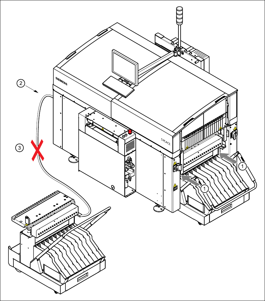
Fig. 2.4 - 1 Safety instructions on the component trolley
User Manual SIPLACE CS 2 Operational safety
Software version SR.101.xx 06/2003 US Edition 2.4 Safety instructions for operating the machine
37
WARNING 2
Æ Never reach into the gap between the component trolley and the placement system frame
(item 1 in Fig. 2.4 - 1
).
Æ Always check that the component trolley is docked on the placement system before connecting
or disconnecting the power cable for the component trolley at the socket on the placement sys-
tem (item 22.4 - 1
).
Æ NEVER connect the connecting cable for the component trolley to the socket on the placement
system and then operate the component trolley outside the machine via the compressed air
control unit (item 3 in Fig. 2.4 - 1).
2.4.2 Safety instructions for lowering the component table bed
WARNING DANGER OF CRUSHING 2
When lowering the component table bed, never reach into the gap between the feeders and the
used tape channel. 2
2.4.3 Safety instructions for changing the table height of component trolleys
WARNING DANGER OF CRUSHING 2
Remove all the feeders from the component table bed, before you adjust the table height of the
component trolley.
Act with considerable care during the conversion process because the table bed is very heavy.
Conversion of the component trolley to other PCB transport heights is described in Section 4.3
on
page 106. 2