Test_Flow_for_Advanced_Packages_WhitePaper_1115.pdf - 第9页
ADV ANCED P ACKAGE TEST FLOW 9 Universal T est Flow for Advanced Packages Despite the dif ferences of the build techniqu e employed with SLIM, 2.5D or 3D, the test flow in Figure 5 defines the univers al test flow that c…
ADVANCED PACKAGE TEST FLOW 8
unit is controlled by the test program which reads the die temperature and regulates the ATC
behavior. The thermal chuck design has to be optimized to avoid pushing down on passives, making
contact with exposed pads and applying uniform pressure on the exposed dies.
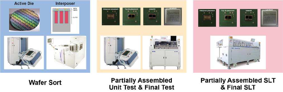
Figure 4: Test Insert Points for Advanced Packages
System Level Tests are usually performed on asynchronous handlers – meaning, each site test
state is independent of the other. Asynchronous handlers allow a device that has failed a test to be
removed and placed in the output tray and a new device inserted into that test socket. In addition to
the modifications needed for device handling and ATC, SLT requires hard disk duplication -
maintaining the same BIOS version and motherboard hardware versions across all test sites. SLT
executes the complete boot sequence and therefore results in long test times (90 to 300 seconds).
Long test time mandates high parallel testing to meet throughput requirements. It is common to run
12 sites in parallel using asynchronous handlers. In these systems, each site has its own tester, which
replicates the target application. This tester could be a PC for a CPU/GPU application or a cell phone
board for an applications processor. The key to successful SLT operations lies in the design on the
test executive that controls and communicates with each individual test site, consolidates test data
files and issues commands to the handler.
ADVANCED PACKAGE TEST FLOW 9
Universal Test Flow for Advanced Packages
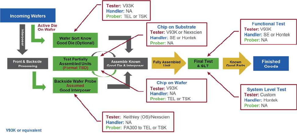
Despite the differences of the build technique employed with SLIM, 2.5D or 3D, the test
flow in Figure 5 defines the universal test flow that can be taken when building such devices. The
test stages are green boxes, while the assembly / middle end of line (MEOL) processes are shown in
black. The incoming and outgoing from the OSAT are shown in blue. The red boxes define the test
equipment used at each stage with a description of the process or test stage.
Figure 5: Test Flow for Advanced Packages
Incoming wafers have two alternate test paths: active wafers are tested as full thickness
wafers and passive interposers with test structures are tested after thinning and mounting on a glass
carrier wafer. If the interposer wafer is tested on an automated prober with a wafer loader, care must
be taken to ensure the prober recognizes the notch on the wafer for orientation. During interposer
test, only the test structures’ connectivity is verified, and if found good, all interconnects on the
interposer die are assumed good.
ADVANCED PACKAGE TEST FLOW 10
Known good die and assumed good interposers are assembled and the partially assembled
unit is sent to test. Depending on the test criteria, the tests can be either opens/ shorts to verify
connectivity or functional tests to check for performance variations. When there are multiple dies on
a single chip, after each die is attached, the partially assembled unit is tested. The form factor at test
will depend on the assembly technique i.e., Chip on Substrate (CoS) or Chip on Wafer (CoW). In the
case of CoW, the material hander is a prober, while in the case of CoS, a final test handler is
employed. This process of partially assembled testing continues as new dies or devices are added to
the unit being built. In the case of CoS, the customer may request that the partially assembled unit be
tested on SLT.
After full assembly, the unit is tested using ATE and, in some cases, is sent to SLT. If the
device is equipped with non-volatile RAM, tracking information such as wafer number, lot number,
die x, y, etc. are written to the device during test, enabling unit level traceability. In some cases, the
device is marked with a 2D barcode that can be scanned to derive the unit level information.
Conclusions
Advanced packages that use SLIM/2.5D or 3D assembly techniques tend to pack high
performance while consuming lower power into a smaller and slimmer package. Each die in the
package in itself is a high performance unit. Integrating these individual dies into a single package
provides improved performance greater than the sum of the individual components if packaged
separately. With the addition of each individual die to the package, the cost of the package increases.
Therefore, it is absolutely necessary to test each individual die for performance prior to assembly
and test the partially assembled units during the assembly process to minimize scrap costs.
Furthermore, with appropriate analysis and package partitioning, each classification of package or
subassembly can be tested in a universal test flow to satisfy the most stringent criteria.