00191457-02.pdf - 第20页
Retrofit instructions Nozzle changer SIPLACE H S-50 / HS-60 / D4 06/2006 Edition 20 2.5 Prep aratory work : Dock the component trolley from its location out of the machine. : Switch the placement mach ine off at the main…
Retrofit instructions Nozzle changer SIPLACE HS-50 / HS-60 / D4
06/2006 Edition
19
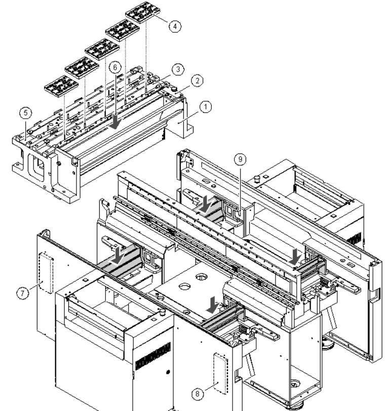
2.4 Position of nozzle changers and sector distribu-
tors
2
Fig. 2 - 1 Position of the nozzle changers and sector distributors
(1) Used tape guide channel
(2) Nozzle ejector device
(3) Location of the 1st nozzle changer
(4) Nozzle magazines
(5) Location of the 2nd nozzle changer
(6) Collecting container for ejected nozzles
(7) Distributor, sector 4
(8) Distributor, sector 1
(9) Opening for the connecting cable and compressed air line
Retrofit instructions Nozzle changer SIPLACE HS-50 / HS-60 / D4
06/2006 Edition
20
2.5 Preparatory work
: Dock the component trolley from its location out of the machine.
: Switch the placement machine off at the main switch.
: Move the gantry to gain easy access to the working surface.
2.6 Installing the 1st nozzle changer
Fig. 2 - 1 shows the locations for installing the first and second nozzle changer for each gantry. 2
2
All the electrical connecting cables and compressed air lines for the nozzle changer are already
installed in placement system. The compressed air lines are sealed with a plug. 2
2
: Remove the plug from the blue compressed air line.
: Attach the y-adapter to the blue compressed air line and seal one end of the y-adapter with a
plug.
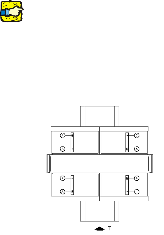
: Before installation, position the nozzle changer (item 1 to 4 in Fig. 2 - 2) so that the opening for
the electrical and pneumatic connections at the bottom (item A in Fig. 2 - 2) is pointing in the
direction shown in Fig. 2 - 1.
2
Fig. 2 - 2 Aligning the nozzle changer for installation
(1) Nozzle changer, gantry 1
(2) Nozzle changer, gantry 2
(3) Nozzle changer, gantry 3
(4) Nozzle changer, gantry 4
A Position of the opening on the bottom
of the nozzle changer for connecting the
control cable and compressed air hose
T PCB transport direction 2
Retrofit instructions Nozzle changer SIPLACE HS-50 / HS-60 / D4
06/2006 Edition
21
2
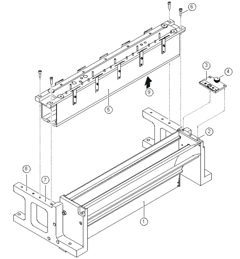
Fig. 2 - 3 Installing the nozzle changer and ejector device
(1) Used tape guide channel
(2) 2 x parallel pins for centering the ejector device
(3) Ejector device
(4) Knurled screw for fixing the ejector device
(5) Nozzle changer
(6) 4 x M4 x 16 hexagon socket-head screws for fixing the nozzle changer
(7) Location of the first nozzle changer
(8) Location of the second nozzle changer
(9) Opening for connecting the control cable and compressed air hose