00191457-02.pdf - 第24页
Retrofit instructions Nozzle changer SIPLACE H S-50 / HS-60 / D4 06/2006 Edition 24 2 Fig. 2 - 5 Connectors and connecting cables
Retrofit instructions Nozzle changer SIPLACE HS-50 / HS-60 / D4
06/2006 Edition
23
2.8 Checking the CAN I/O module connectors in sector
distributor 4
: Loosen the six hexagon socket-head screws and then remove the placement system cover
from sector distributor 4 (item 7 in Fig. 2 - 1).
2
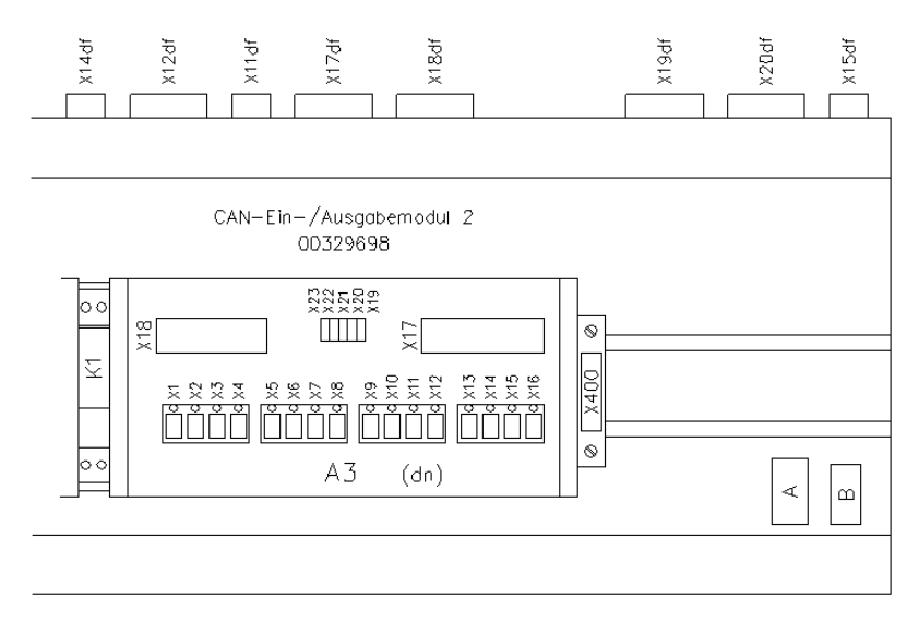
Fig. 2 - 4 CAN I/O module 2 in sector distributor 4 for controlling the 1st nozzle changer
2
: CAN I/O module 2 in sector distributor 4 for controlling the 1st nozzle changer
: Check all the connectors on CAN I/O module 2 (A3) as shown in Fig. 2 - 4.
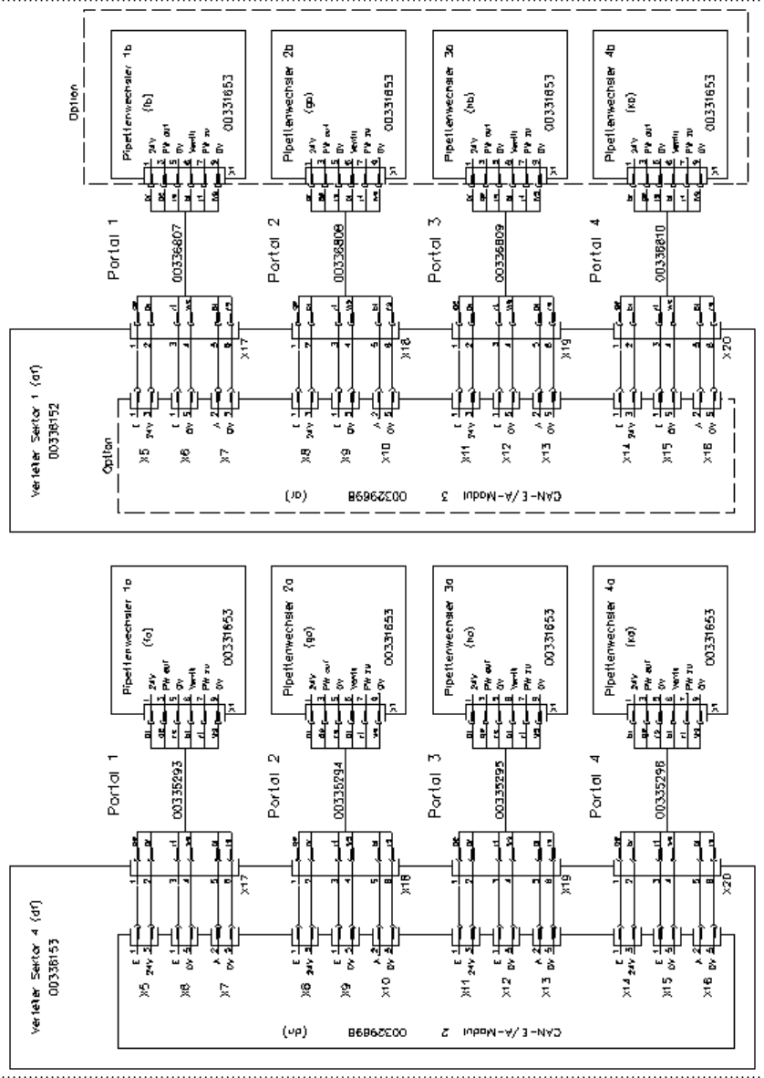
The assignment of plugs and connecting cables to nozzle changers is shown in Fig. 2 - 5.
: Check the address set for CAN I/O module 2: address: 28CH
Plug number Jumper
X19 Yes
X20 No
X21 No
X22 No
X23 No
Retrofit instructions Nozzle changer SIPLACE HS-50 / HS-60 / D4
06/2006 Edition
24
2
Fig. 2 - 5 Connectors and connecting cables
Retrofit instructions Nozzle changer SIPLACE HS-50 / HS-60 / D4
06/2006 Edition
25
2.9 Installing CAN I/O module 3 in sector distributor 1
: Loosen the six hexagon socket-head screws and then remove the placement system cover
from sector distributor 1 (item 8 in Fig. 2 - 1).
2
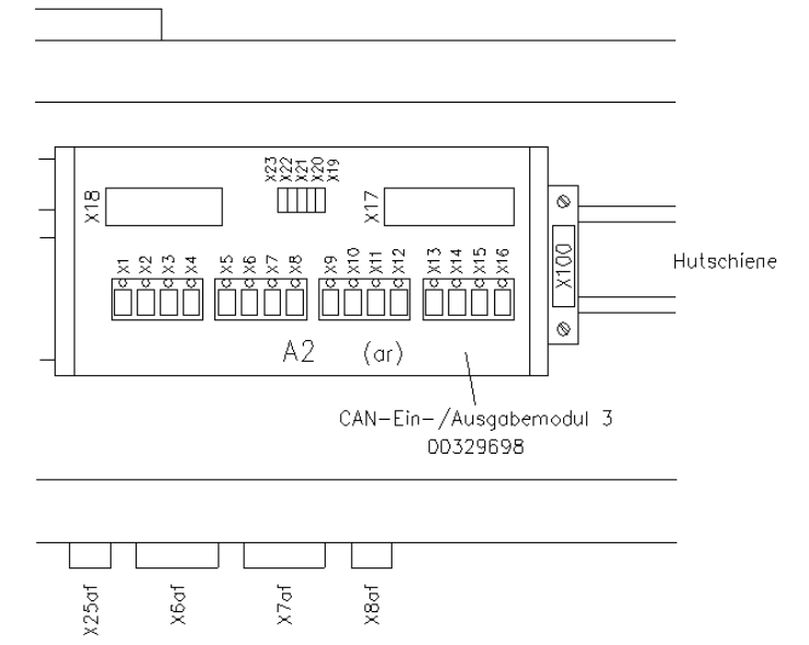
Fig. 2 - 6 CAN I/O module 3 in sector distributor 1 for controlling the 2nd nozzle changer
2
: Clip the CAN I/O module (item no. 00329698-xx) onto the top-hat rail (see Fig. 2 - 6).
: Plug the numbered cable connectors into slots X5 to X18. The assignment of plugs and con-
necting cables to nozzle changers is shown in Fig. 2 - 5.
: Slot number on CAN I/O module 3
X1 - X4 Not used
X5 - X7 2nd nozzle changer, gantry 1
X8 - X10 2nd nozzle changer, gantry 2
X11 - X13 2nd nozzle changer, gantry 3
X14 - X16 2nd nozzle changer, gantry 4
X17 Plug connector for cable 00336801
X18 Plug connector X18ar for cable 00335324-xx