00191457-02.pdf - 第23页
Retrofit instructions Nozzle changer SIPLACE HS-50 / HS-60 / D4 06/2006 Edition 23 2.8 Checking the CAN I/O module connectors in sector distributor 4 : Loosen the six hexagon socket-head scre ws and then remove the place…

Retrofit instructions Nozzle changer SIPLACE HS-50 / HS-60 / D4
06/2006 Edition
22
: Plug the control cable into the control board and secure with the two screws.
The following table shows which control cables can be connected to each nozzle changer.
2
: Make sure that the contact surface (item 7 and 8 in Fig. 2 - 3) between the nozzle changer and
the used tape guide channel is clean.
: Place the nozzle changer (item 5 in Fig. 2 - 3) on the used tape guide channel (item 1 in Fig.
2 - 3) at the point identified by item 7 in Fig. 2 - 3.
: Start by loosely tightening the four M4 x 16 hexagon socket-head screws (item 6 in Fig. 2 - 3).
: Then fully tighten the four M4 x 16 hexagon socket-head screws in a diagonally opposite se-
quence.
: Attach the blue compressed air hose of the nozzle changer to the y-adapter.
2
2.7 Installing the ejector device
: Position the ejector device (item 4 in Fig. 2 - 3) so that the two holes in the device are aligned
with the two parallel pins (item 2 in Fig. 2 - 3) on the used tape guide channel.
: Insert the ejector device and fix in place with the knurled screw (item 4 in Fig. 2 - 3).
2
2
2
2
2
2
Cable number Nozzle changer location (see Fig. 2 - 1)
00335293-xx
00335807-xx
No.1 Gantry 1
No. 2 Gantry 1
00335294-xx
00335808-xx
No.1 Gantry 2
No. 2 Gantry 2
00335295-xx
00335809-xx
No.1 Gantry 3
No. 2 Gantry 3
00335296-xx
00335810-xx
No.1 Gantry 4
No. 2 Gantry 4
Tab. 2 - 1 Assignment of control cables to nozzle changer locations
Retrofit instructions Nozzle changer SIPLACE HS-50 / HS-60 / D4
06/2006 Edition
23
2.8 Checking the CAN I/O module connectors in sector
distributor 4
: Loosen the six hexagon socket-head screws and then remove the placement system cover
from sector distributor 4 (item 7 in Fig. 2 - 1).
2
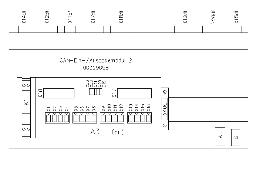
Fig. 2 - 4 CAN I/O module 2 in sector distributor 4 for controlling the 1st nozzle changer
2
: CAN I/O module 2 in sector distributor 4 for controlling the 1st nozzle changer
: Check all the connectors on CAN I/O module 2 (A3) as shown in Fig. 2 - 4.
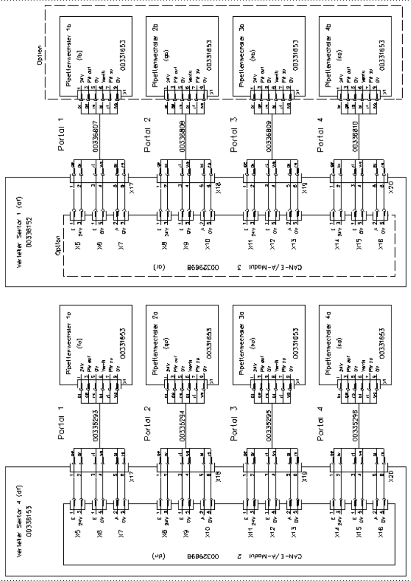
The assignment of plugs and connecting cables to nozzle changers is shown in Fig. 2 - 5.
: Check the address set for CAN I/O module 2: address: 28CH
Plug number Jumper
X19 Yes
X20 No
X21 No
X22 No
X23 No
Retrofit instructions Nozzle changer SIPLACE HS-50 / HS-60 / D4
06/2006 Edition
24
2
Fig. 2 - 5 Connectors and connecting cables