00191457-02.pdf - 第25页
Retrofit instructions Nozzle changer SIPLACE HS-50 / HS-60 / D4 06/2006 Edition 25 2.9 Inst alling CAN I/O module 3 in sector distributor 1 : Loosen the six hexagon socket-head scre ws and then remove the placemen t syst…
Retrofit instructions Nozzle changer SIPLACE HS-50 / HS-60 / D4
06/2006 Edition
24
2
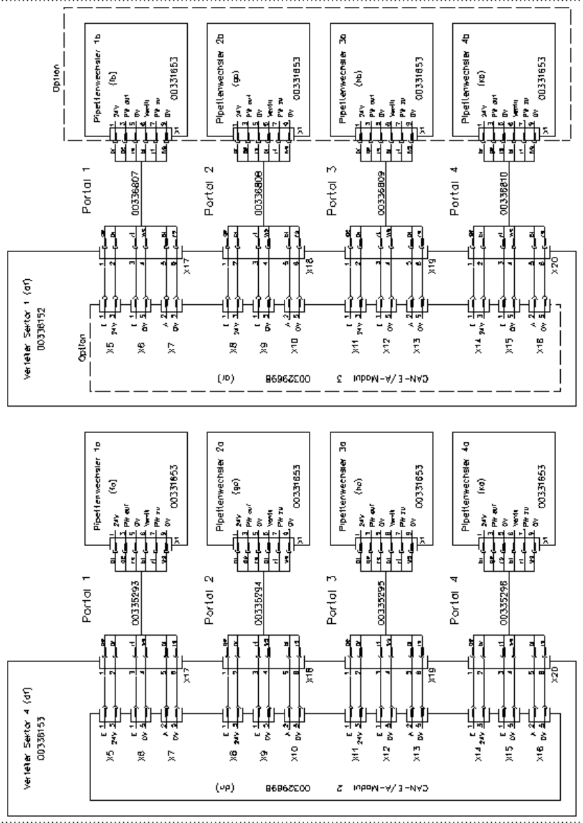
Fig. 2 - 5 Connectors and connecting cables
Retrofit instructions Nozzle changer SIPLACE HS-50 / HS-60 / D4
06/2006 Edition
25
2.9 Installing CAN I/O module 3 in sector distributor 1
: Loosen the six hexagon socket-head screws and then remove the placement system cover
from sector distributor 1 (item 8 in Fig. 2 - 1).
2
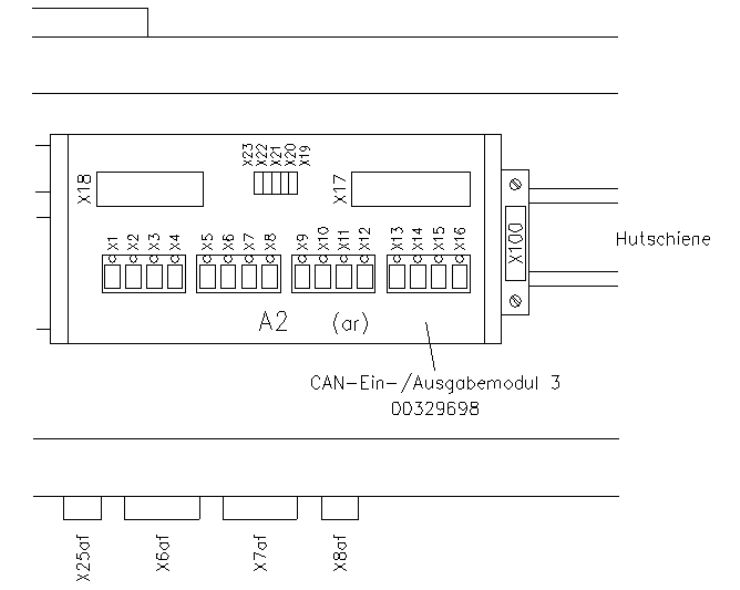
Fig. 2 - 6 CAN I/O module 3 in sector distributor 1 for controlling the 2nd nozzle changer
2
: Clip the CAN I/O module (item no. 00329698-xx) onto the top-hat rail (see Fig. 2 - 6).
: Plug the numbered cable connectors into slots X5 to X18. The assignment of plugs and con-
necting cables to nozzle changers is shown in Fig. 2 - 5.
: Slot number on CAN I/O module 3
X1 - X4 Not used
X5 - X7 2nd nozzle changer, gantry 1
X8 - X10 2nd nozzle changer, gantry 2
X11 - X13 2nd nozzle changer, gantry 3
X14 - X16 2nd nozzle changer, gantry 4
X17 Plug connector for cable 00336801
X18 Plug connector X18ar for cable 00335324-xx

Retrofit instructions Nozzle changer SIPLACE HS-50 / HS-60 / D4
06/2006 Edition
26
: Check the address set for CAN I/O module 3: address: 294H
Plug number Jumper
X19 No
X20 Yes
X21 No
X22 No
X23 No
2.10 Settings
: Switch on the placement system.
: Press the Start button when you see the prompt.
: Configure the nozzle changer in the line computer configuration editor.
: Use the SITEST program to calibrate each nozzle changer.
: Determine the z height for each magazine.
2.11 Commissioning the nozzle changer
: When you fill a magazine with a certain nozzle type for the first time, attach an adhesive label
to identify the type.
2
Only ONE nozzle type must be used in each magazine.
Fill the magazines off the machine and always replace complete magazines. 2
2
: Open the locking plate and place the nozzles in the nozzle garages.
: Close the locking plate so that the nozzles cannot drop out of the magazines.
2
Before you fill magazine, make sure that all the nozzles on the revolver head have been returned
to their magazines. 2
2
2
: Do not allow components to drop onto the magazines. If they do, they could jam the locking
plate.
: Do not allow components to drop onto free feeder module locations because they will stick to
the magnetic bar. Production may have to be interrupted if the feeder modules are not placed
on the component table correctly. You should therefore regularly clean the magazines and free
locations.