00191457-02.pdf - 第22页
Retrofit instructions Nozzle changer SIPLACE H S-50 / HS-60 / D4 06/2006 Edition 22 : Plug the control cable into the co ntrol board and secure with the two screws. The following t able shows which control cables can be …
Retrofit instructions Nozzle changer SIPLACE HS-50 / HS-60 / D4
06/2006 Edition
21
2
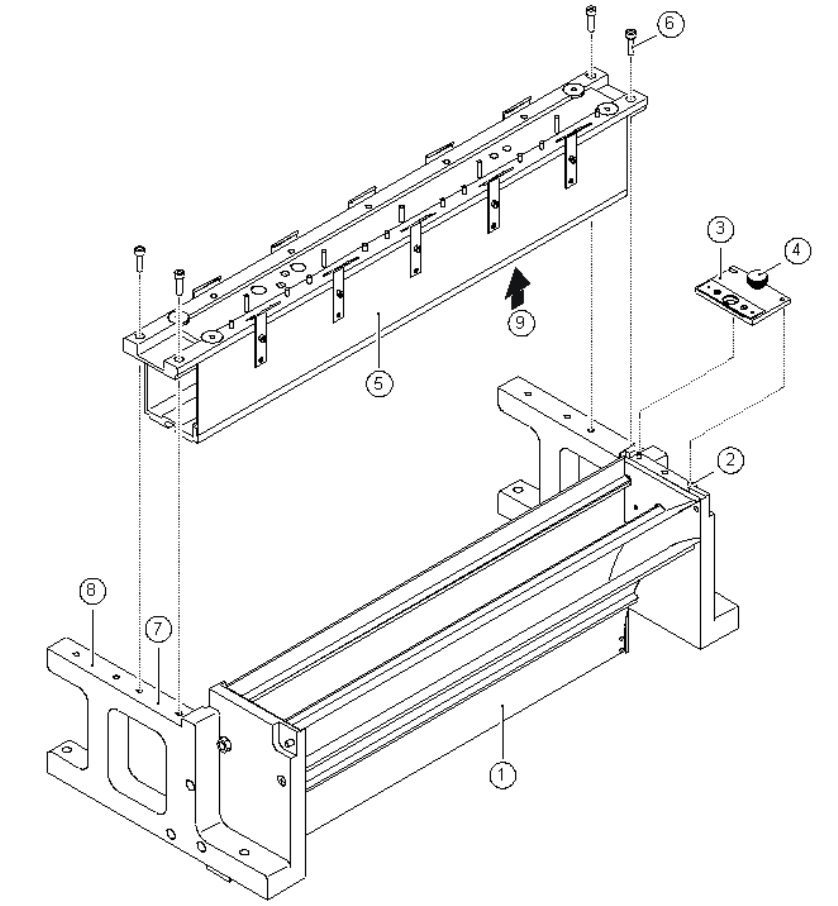
Fig. 2 - 3 Installing the nozzle changer and ejector device
(1) Used tape guide channel
(2) 2 x parallel pins for centering the ejector device
(3) Ejector device
(4) Knurled screw for fixing the ejector device
(5) Nozzle changer
(6) 4 x M4 x 16 hexagon socket-head screws for fixing the nozzle changer
(7) Location of the first nozzle changer
(8) Location of the second nozzle changer
(9) Opening for connecting the control cable and compressed air hose

Retrofit instructions Nozzle changer SIPLACE HS-50 / HS-60 / D4
06/2006 Edition
22
: Plug the control cable into the control board and secure with the two screws.
The following table shows which control cables can be connected to each nozzle changer.
2
: Make sure that the contact surface (item 7 and 8 in Fig. 2 - 3) between the nozzle changer and
the used tape guide channel is clean.
: Place the nozzle changer (item 5 in Fig. 2 - 3) on the used tape guide channel (item 1 in Fig.
2 - 3) at the point identified by item 7 in Fig. 2 - 3.
: Start by loosely tightening the four M4 x 16 hexagon socket-head screws (item 6 in Fig. 2 - 3).
: Then fully tighten the four M4 x 16 hexagon socket-head screws in a diagonally opposite se-
quence.
: Attach the blue compressed air hose of the nozzle changer to the y-adapter.
2
2.7 Installing the ejector device
: Position the ejector device (item 4 in Fig. 2 - 3) so that the two holes in the device are aligned
with the two parallel pins (item 2 in Fig. 2 - 3) on the used tape guide channel.
: Insert the ejector device and fix in place with the knurled screw (item 4 in Fig. 2 - 3).
2
2
2
2
2
2
Cable number Nozzle changer location (see Fig. 2 - 1)
00335293-xx
00335807-xx
No.1 Gantry 1
No. 2 Gantry 1
00335294-xx
00335808-xx
No.1 Gantry 2
No. 2 Gantry 2
00335295-xx
00335809-xx
No.1 Gantry 3
No. 2 Gantry 3
00335296-xx
00335810-xx
No.1 Gantry 4
No. 2 Gantry 4
Tab. 2 - 1 Assignment of control cables to nozzle changer locations
Retrofit instructions Nozzle changer SIPLACE HS-50 / HS-60 / D4
06/2006 Edition
23
2.8 Checking the CAN I/O module connectors in sector
distributor 4
: Loosen the six hexagon socket-head screws and then remove the placement system cover
from sector distributor 4 (item 7 in Fig. 2 - 1).
2
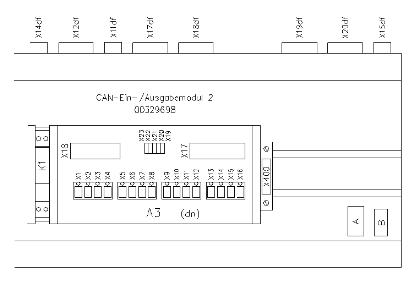
Fig. 2 - 4 CAN I/O module 2 in sector distributor 4 for controlling the 1st nozzle changer
2
: CAN I/O module 2 in sector distributor 4 for controlling the 1st nozzle changer
: Check all the connectors on CAN I/O module 2 (A3) as shown in Fig. 2 - 4.
The assignment of plugs and connecting cables to nozzle changers is shown in Fig. 2 - 5.
: Check the address set for CAN I/O module 2: address: 28CH
Plug number Jumper
X19 Yes
X20 No
X21 No
X22 No
X23 No