circuit of HS60.pdf - 第170页
5 - 38 0036276 6-010 101ND 4 984 board, conversi on b oard, l ifting table Sta t. 01 Modi fie d 04.04.01 Date KD Name PC board Dorfn er 04. 04 .0 1 MCHN R/ Tu SIEM ENS AG ATD T D E Date Name Compo nent l ayout, c omponen…
5 - 37
00359425-020101ND4 962 board, conversion board, conveyor 1,
connector assignment (Sh. 3 of 3)
G32918 - M0069 - U021 - * - 17
01
Stat. Modified Date
12.12.00
Name
KD
ATD TD E
SIEMENS AG
MCHN R/Tu
12.12.00
Dorfner
PC board
Date
Name
2-layer
00359425-020101ND4
Conversion board
PC board
Scale
1 : 1
Sheet
3 -
962
Conveyor 1
KD04.04.0102
KD10.07.0104
5, 6
4
3+24V
GND
Key
--> X52.202
1
2
3, 4
5, 6
Key
--> X52.22
+24V
GND
2
3, 4
5
6
--> X52.24
+24V
Key
GND
1, 2
3 ... 34
37 ... 48
49, 50
+24V
GND
1, 2
3 ... 36
39, 40
+24V
GND
1, 2
3, 4
5, 6
7, 8
9, 10
11, 12
13, 14
15, 16
17, 18
19, 20
21, 22
23
24
25
26
27
28
29
30
31
32
33, 34
MOTOR 1+
MOTOR 1-
MOTOR 2+
MOTOR 2-
MOTOR 3+
MOTOR 3-
MOTOR 4+
MOTOR 4-
MOTOR 5+
MOTOR 5-
GND
--> X52.27
--> X52.28
--> X52.29
--> X52.30
--> X52.31
--> X52.7
--> X52.8
--> X52.15
--> X52.27
--> X52.11
+24V
1, 2
3, 4
5, 6
7, 8
9, 10
11, 12
13, 14
15, 16
17, 18
19, 20
25, 26
27, 28
29, 30
31, 32
MOTOR 1+
MOTOR 1-
MOTOR 2+
MOTOR 2-
MOTOR 3+
MOTOR 3-
MOTOR 4+
MOTOR 4-
MOTOR 5+
MOTOR 5-
SM_A+
SM_A-
SM_B+
SM_B-
1, 2
3, 4
5, 6
7, 8
9, 10
11, 12
13, 14
15, 16
17, 18
19, 20
21, 22
28
29
30
31
32
33, 34
MOTOR 1+
MOTOR 1-
MOTOR 2+
MOTOR 2-
MOTOR 3+
MOTOR 3-
MOTOR 4+
MOTOR 4-
MOTOR 5+
MOTOR 5-
GND
--> X52.9
--> X53.28
--> X52.16
--> X52.41
--> X52.42
+24V
Connector X46/width adjustment
Adjustment drive 2, cylinder switch Connector X51
Connector X55 / cheeks B/D
Connector X47/width adjustment
Adjustment drive 2, prox.sw. f. cheek
Connector X48/width adjustment
Limit switch, spindle on the left
Connector X52
Connector X53
Connector X54/cheeks A/C
5 - 38
00362766-010101ND4 984 board, conversion board, lifting table
Stat.
01
Modified
04.04.01
Date
KD
Name
PC board
Dorfner
04.04.01
MCHN R/Tu
SIEMENS AG
ATD TD E
Date
Name
Component layout, component side
G32918 - N0032 - U201 - * - 17
Conversion board
00362766-010101ND4
PC board
Scale
1 : 1
1 -
Sheet
984
2-layer
A Assembly designation 11x13 (solder side)
B Inspection label (solder side)
Lifting table
1
2
3
6
2
3
4
6
2
3
5
6
1
2
3
6
2
3
4
6
1
2
3
4
5
6
10
Connector X1
Connector X2
Connector X3
Connector X4
Connector X5
Connector X6
Key
Track A
+24V
GND
Key
Track B
+24V
GND
Key
+24V
Limit switch
GND
GND
+24V
Valve "up"
Key
GND
+24V
Valve "down"
Key
+24V
Track A
Track B
Limit switch
Valve "up"
Valve "down"
GND
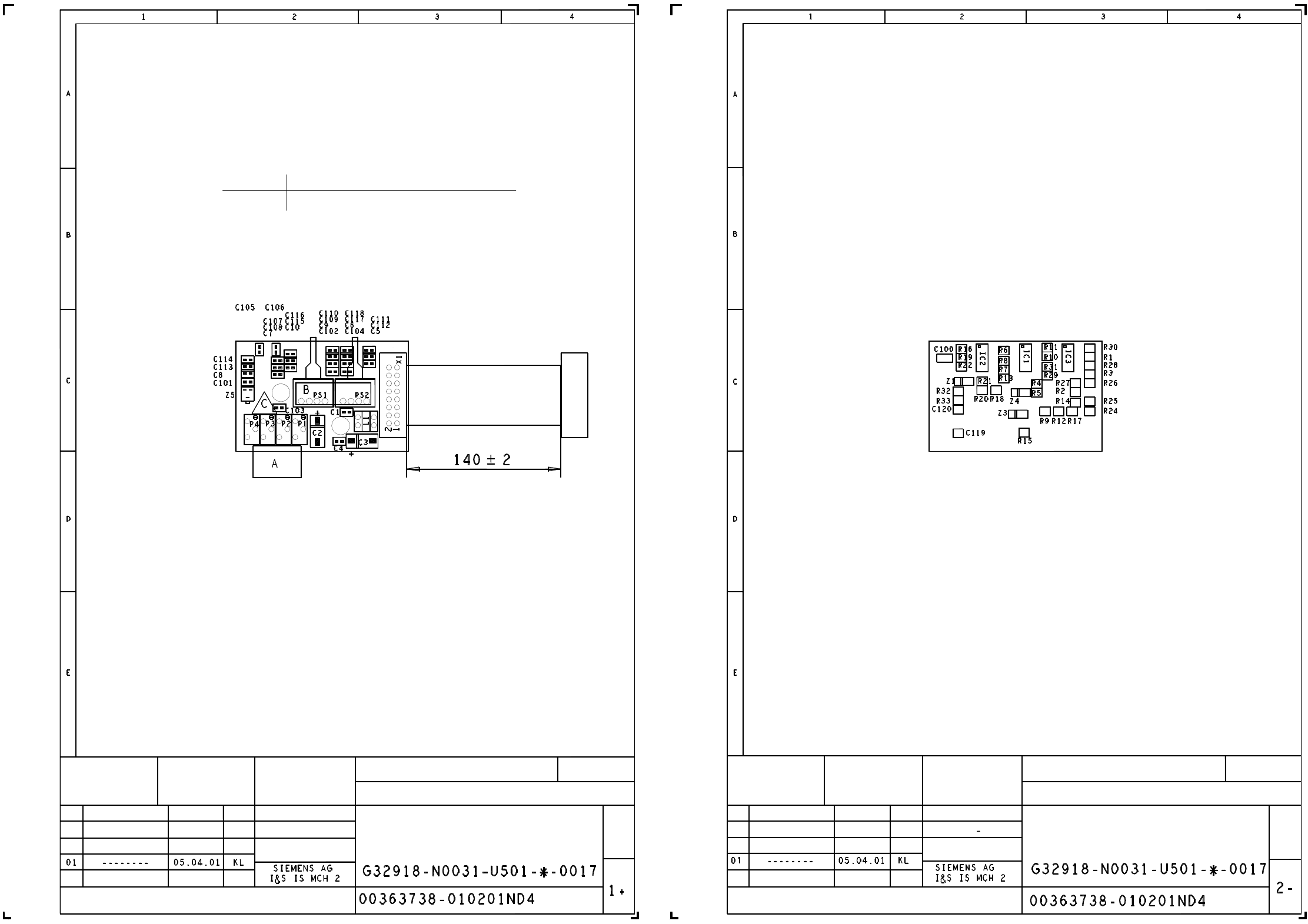
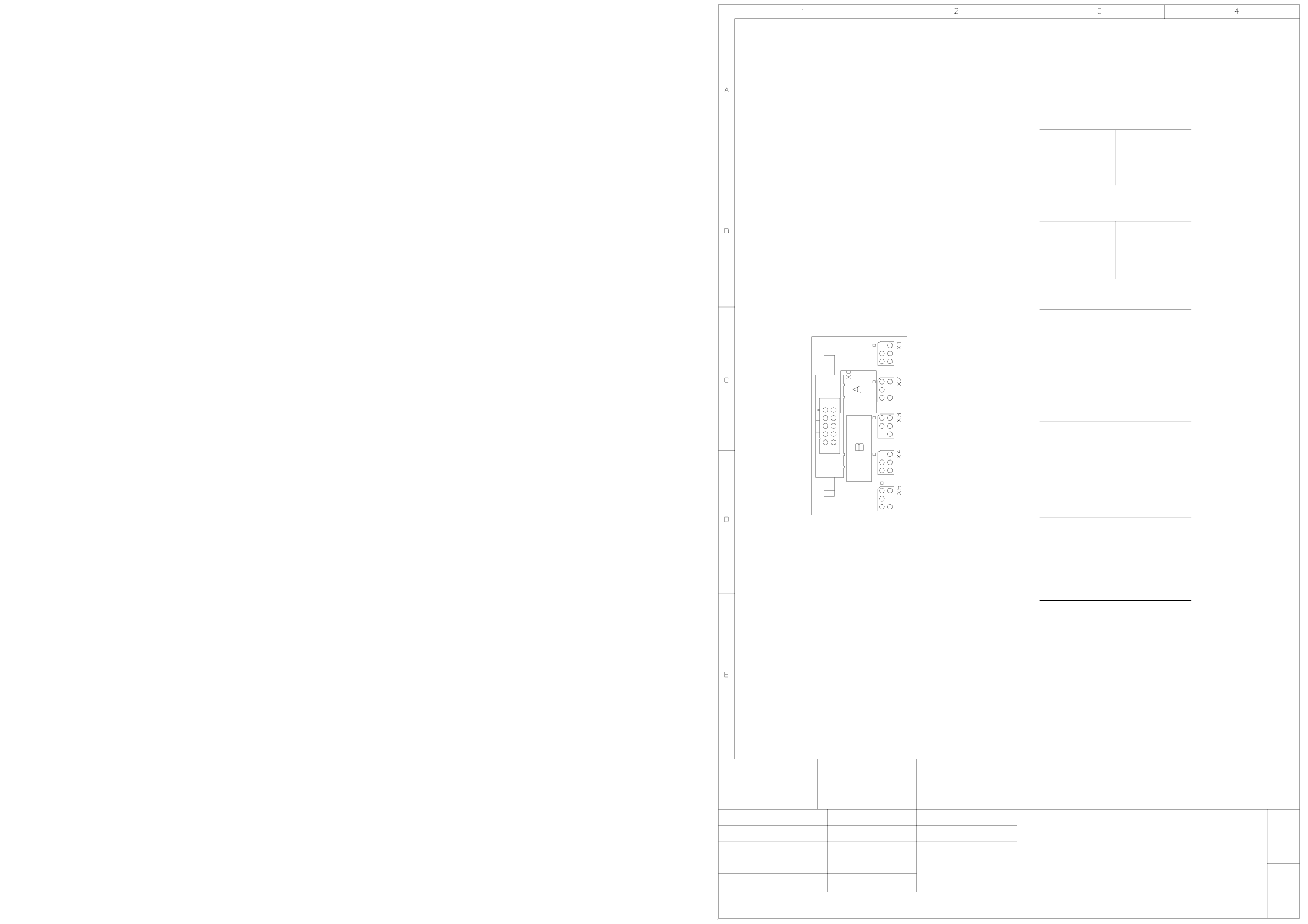
5 - 39
00363738-010201ND4 983 board, vacuum board (2 sectors) (Sh. 1 of 2)
00363738-010201ND4 983 board, vacuum board (2 sectors) (Sh. 2 of 2)
C = ESD-LABEL
B = INSPECTION LABEL ON PRESSURE SENSORS
A = IDENTIFICATION LABEL, LATERAL TO P1-P4
Status
Note
Date
Name
Date
Name
M 1:1
4-layer PCB
Placement diagram component side
PCB 983
VACUUM BOARD (2 MEAS. RANGES)
05.04.01
KLOSE
Assembly
X10 gantry head distributor 00344487
Connector
X1
Sheet
05.04.01
KLOSE
State
Note
Date
Name
Name
Date
M 1:1
4-layer PCB
Placement diagram soldering side
PCB 983
VACUUM BOARD (2 MEAS. RANGES)
Sheet