circuit of HS60.pdf - 第181页
6 - 2 0032406 5-020 102X D3 SIPLACE tape cutter, pneumatica lly op erated SF 1 0032 4065-020 102X D 3 Tap e cu tter, pn eum atic ally o pera ted Sipl ace HS60 18.11 .97 Bernd l ---- nn.nn.nn 23.02.98 Bern Name Stat us Da…
6 - 1
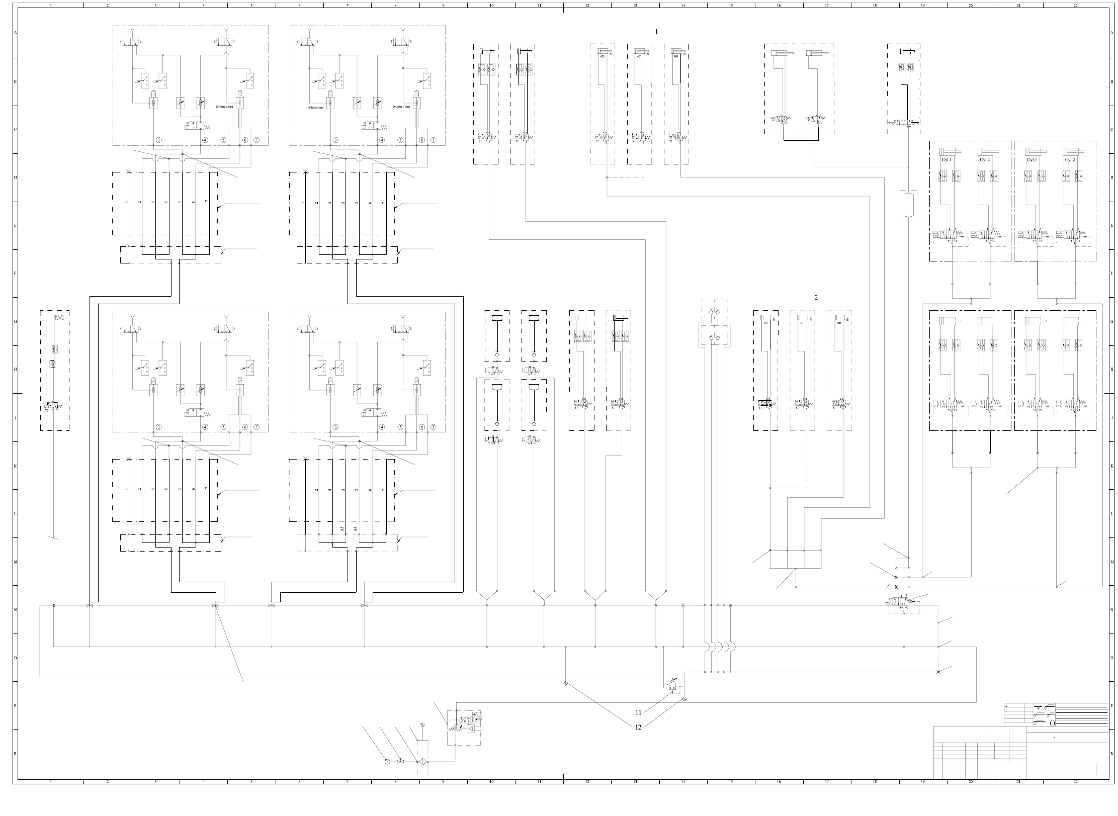
6 Pneumatic Diagrams
00329906-040201XD0 HS-60 pneumatic system, pneumatic diagram
4 3
2 1
PUN-4
PUN-4
PUN-4
PUN-4
ES 02 Ae. 11796 21.05.02 Fu.
NN ± N
1
A0
1710xxx Xxxxx xxx xx P
Tiefe:0,3/
2-5 um chemisch vernickelt
00329906-040201XD0
Futterer18.07.01
1
FSUA
SIEMENS
AUT 5
<6
>6...30
>30...120
>120...400
>400...1000
±0,1
±0,2
±0,3
±0,5
±0,8
Oberfl.:
gehÌrtet HRc
ein satzge hÌrtet
z
R 100
z
R 25
z
R 6,3
z
R 1
Hierzu gehoert
Koordinatenliste:
PUN-4
PUN-4
PUN-4
PUN-4
PUN-8
PUN-8
PUN-8
PUN-8
E3
E2
E1
A1
A2
A4
A5
A3
A6
A7
A1
A2
A4
A5
A3
A6
A7
E3
E2
E1
E3
A1
A2
A4
A5
A3
E2
E1
A6
A7
E3
E2
E1
A1
A2
A4
A6
A7
EZH-2,5/9-10
PUN-6
PUN-6
PUN-6
PUN-6
PAN-6
PUN-4
PUN-4
PUN-4
PUN-4
PUN-4
PUN-4
PUN-4
PUN-4
20h
(20i)
20,a,b,c,d,e
4 3
2
10b
1
10c
1
24
6,6a,6c
10
14
3,3a
20g
00336911-01
QSY-6
QSY-6
QSY-8-6
centering
(Option)
Substrate
Speed-Placer 6-12 Speed-Placer 6-12
(Option)
changer
Nozzle
(Option)
changer
Nozzle
Holding circuit
Forced air
Forced air
Holding circuit
Forced air
Forced air
Placement circuit
7-fold hose
Trailing cable
7-fold hose
Trailing cable
Gantry 4
Distributor for
Distributor for
Gantry 3
Speed-Placer 6-12
Speed-Placer 6-12
(Option)
PCB stopper
(Option)
PCB stopper
(Option)
PCB stopper
Width adjustment
Lifting table
Right track
Tape cutter
4 on the left 3 on the right
Compressed-air store
Ø 40 ; stroke 30 Ø 40 ; stroke 30 Ø 40 ; stroke 30 Ø 40 ; stroke 30
Valve 1 Valve 2 Valve 1 Valve 2
Ø 40 ; stroke 30 Ø 40 ; stroke 30 Ø 40 ; stroke 30 Ø 40 ; stroke 30
Cyl.1 Cyl.2 Cyl.1 Cyl.2
Valve 2Valve 1Valve 2Valve 1
Bulk case
Connecting
(Option)
PCB stopper
(Option)
PCB stopper
(Option)
PCB stopper
Feeder
(Option)
Left track
TableTable
Table Table
(Option)
changer
NozzleComponent table
(Option)
changer
Nozzle
Table Table
Table Table
5.5 bar
5.5 bar
Holding circuit
Forced air
Forced air
Placement circuit
nozzle dia. 1mm
nozzle dia. 1.5mm
Holding circuit
Forced air
Forced air
nozzle dia. 1.5mm
nozzle dia. 1mm
Placement circuit
Gantry 4
Trailing cable
7-fold hose
Distributor for
Gantry 1
Gantry 2
Gantry 1
Gantry 3
Distributor for
Gantry 2
Trailing cable
7-fold hose
Valve block
*) Nozzle shut !
Dimensional variations
acc. to ISO 2 768 mH
Degree of accuracy
Dimens. variations:
medium
Scale
(Material, semifinished products)
(Unmachined part no.)
(Model or swage no.)
HS60 pneumatic system
Pneumatic diagram
(Drawing number)
Main no. FS PS DS
Sheet
Sh.
NameDate
Author
Check.
Stand.
St atus M odifi ed Da te Nam e
FS 04 neu 18.07.01 Fu.
the pneumatic label, mat. no. 00345740-02!
When modifications are made, please observe
p = 2.5 ± 0.5 bar
p = 5.4 ± 0.1 bar
NOMINAL value
internal
external
digital
8 Bit
p = 5.5 - 10 bar
( at 950Nl/min. compressed air consumption )
1 on the right2 on the left
Format
Weitergabe sowie Vervielfaeltigung dieser Unterlage, Verwer-
tung und Mitteilung ihres Inhalts nicht gestattet, soweit nicht
ausdruecklich zugestanden. Zuwiderhandlungen verpflichten zu
Schadenersatz. Alle Rechte fuer den Fall der Patenterteilung
oder GM-Eintragung vorbehalten.
Copying of this document, and giving it to othe rs and th e use
or communication of the contents thereof, are forbidden with-
out express authority. Offenders are liable to the payment of
damages. All rights are reserved in the event of the grant of
a patent or the registration of a utility model or design.
PUN-8 PUN-6
B5.4
B5.1 B5.2 B5.3
B11
B16.4
B16.3
B13.2
B13.1
B12.2
B12.1
B16.1
B16.2
B2
B1
B10
B8
B17
B6
B4
B7
PUN-4
PUN-4
PUN-4
PUN-4
PUN-4
00345733-0100345733-01
00345185-01
00345185-01
PU2
PUN-4
PUN-4
PUN-4
6 - 2
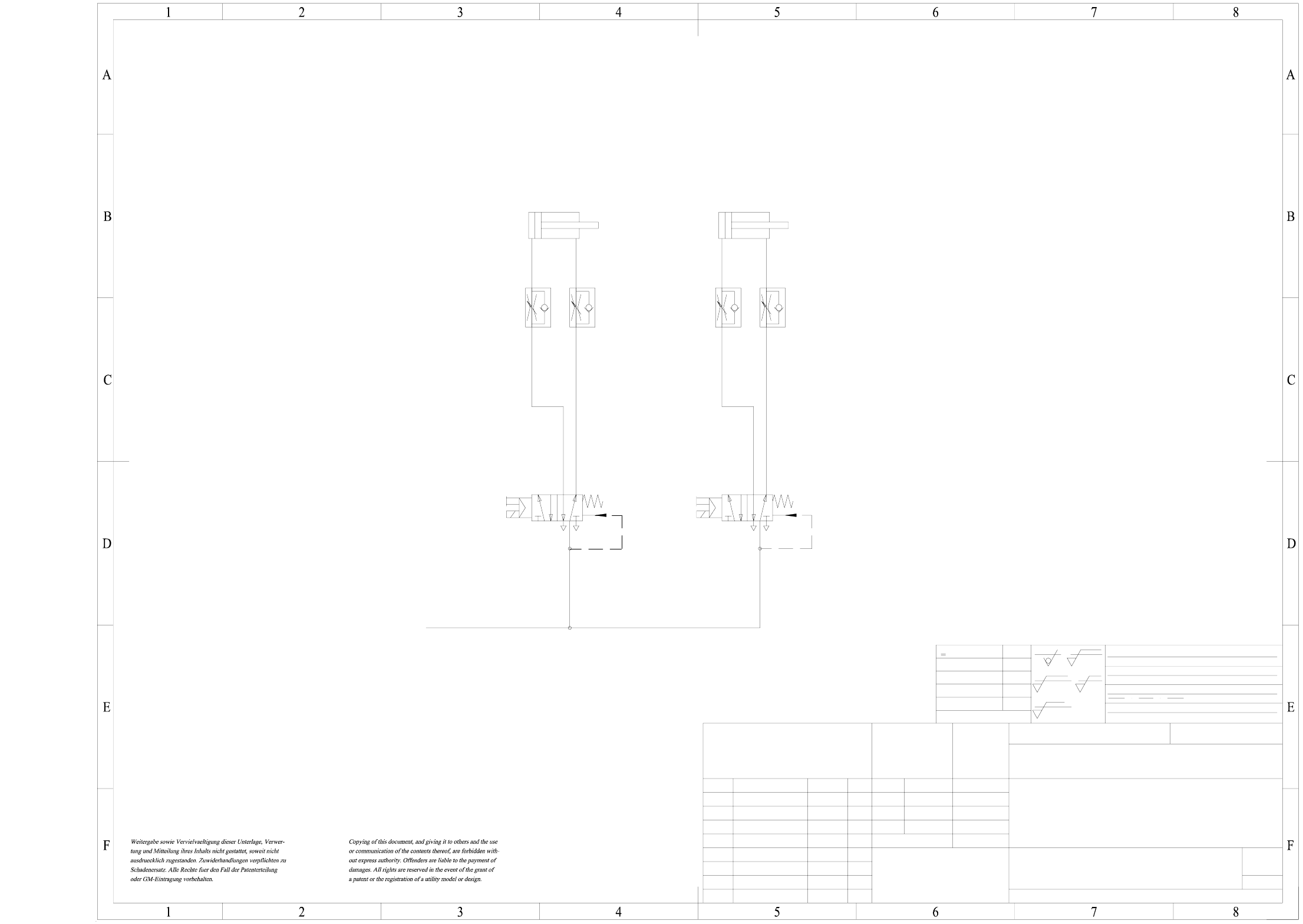
00324065-020102XD3 SIPLACE tape cutter, pneumatically operated
SF
1
00324065-020102XD3
Tape cutter, pneumatically operated
Siplace HS60
18.11.97
Berndl
----
nn.nn.nn
23.02.98
Bern
Name
Status
Date
DS 01
DS 02
new
Pressure entered
Modified
Dimensional variations
Dimension.variations:
Degree of accuracy
medium
acc. to ISO 2768 mH
NameDate
Stand.
Author
Check.
Main no.
(Drawing number)
Format
Scale
(Material, semifinished products)
(Model or swage no.)
(Unmachined part no.)
Drawings 2/A
5.2 bar
2-5 µm chemisch vernickelt
Tiefe:0,3/
1710xxx Xxxxx xxx xx P
A3
1
NN ± N
()
Valve 1
ba
2
3
4
1
5
Valve 2
ba
2
3
4
1
5
Compressed air supply
of servicing unit
machine
Cyl.1
Ø 40 ; Stroke 30
Cyl.2
Ø 40 ; Stroke 30
Sheet
Sh.
Hierzu gehoert
Koordinatenliste:
R 1
z
R 6,3
z
R 25
z
R 100
z
einsatzgehaertet
gehaertet HRc
Oberfl.:
±0,8
±0,5
±0,3
±0,2
±0,1
>400...1000
>120...400
>30...120
>6...30
<6
AUT 5
SIEMENS
FS ES US UA
6 - 3
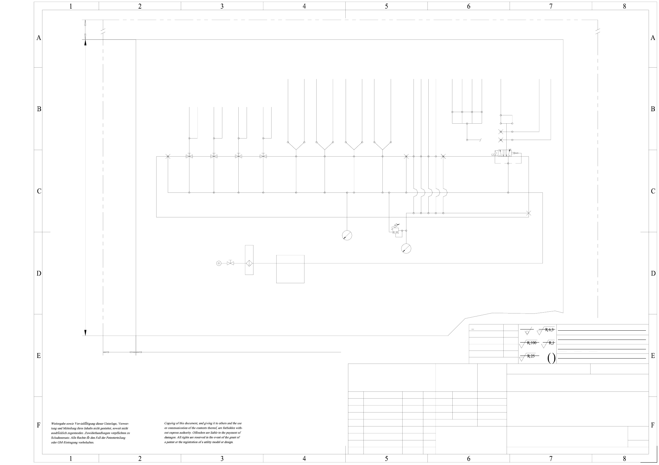
00345740-020101ND3 HS-60 pneumatic system, layout f. pneumatic labels
NN ± N
1
A3
1710xxx Xxxxx xxx xx P
Tiefe:0,3/
2-5 um chemisch vernickelt
50
20
1
00345740-020101ND3
1:1
Scotchcal 3698-E
19.01.99 Ried
FSUA
SIEMENS
PL EA
<6
>6...30
>30...120
>120...400
>400...1000
±0,1
±0,2
±0,3
±0,5
±0,8
Oberfl.:
gehaertet HRc
einsatzgehaertet
Hierzu gehoert
Koordinatenliste:
B10
B5.4 B5.1 B5.2 B5.3 B13.2 B13.1 B12.2 B12.1 B11
B7 B4 B6
B16.4
B16.1
B16.2
B16.3
B17
B1
B2
B8
260
180
Bulk case
Component table
Nozzle
changer Feeder
Compressed air store
PCB stopper
(Option)
Tape
cutter
BCF 4
BCF 1
BCF 2
BCF 3
Sector 4
Sector 3
Table 3
Sector 1
Table 4
Table 1
Table 2
Sector 2
Gantry 2
Gantry 4
Gantry 1
Spare
Gantry 3
Left track 2
Left track 2
Right track 1
Right track 1
Sector 1/2
Sector 3/4
Valve block
p = 5.2 bar
Filter
Sentronic valve
p = 2.5 ±0.5 bar
(at 950Nl/min
compressed-air consumption)
p min = 6.5 bar
Fit on the inside of door
of assembly 00330349-02
Status Modified Date Name
DS 01 new nn.nn.nn ----
FS 02 HHS60 09.05.01 Fu.
Dimension. variations:
Degree of accuracy
medium
acc. to ISO 2768 mH
Date
Name
Author
Check.
Stand.
(Drawing number)
Main no.
HS60 Pneumatic system
Layout for pneumatic label
(Material, semifinished products)
(Unmachined part no.)
(Model or swage no.)
Farbe Al RAL 9006
Scale
Format
Dimensional variations
Sheet
Sh.
FS PS DS
Contour of 00330349-02