AUROTEK_PCB+Separator多机型介绍.pdf - 第5页
Setting Fixture 2 stations Working Area X:330mm Y:330mm Z:15mm Component Height Top side:15mm, Bottom side:45mm PCB Thickness 0.5 ~ 2mm (It’s necessary to contact Aurotek in advance for over 2mm ) Routing Bit Diameter Ø1…
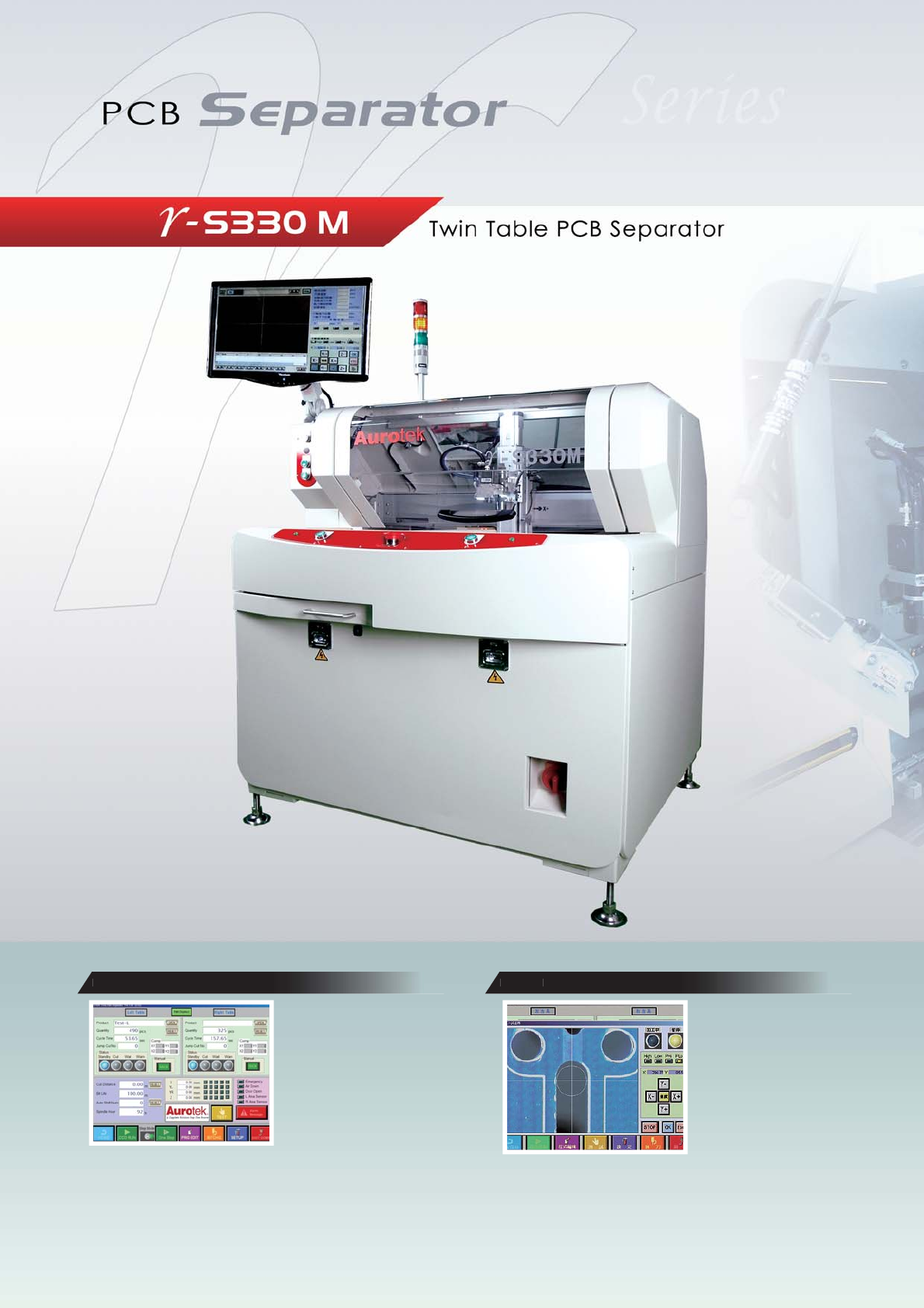
High Speed
High Reliability
Low Pollution
W
indow
s
CCD
CCD image could check &
simulate the path of routing to
reduce unnecessary mistake
before cutting.
x 10 zoom-in image makes
programming easier & increase
the accuracy of point setting.
視窗程式介面,影像輔助路徑編
輯,操作簡單易懂,定位精確,縮
短程式製作時間。
程式編輯後,加工切割前,利用CCD
影像模擬檢查預定切割位置,可避免
因程式編輯錯誤時造成損失。
Windowsシステムとグラフィカル・
ユーザ・インタフェース(GUI)を
採用している為、操作が分りやすく
簡単。10倍ズームCCDカメラによる、切断ポイントの編集が画面にて確認す
る事が可能となり、操作ミスや加工損失を最小限に抑える事ができます。ま
た、設定時間も大幅短縮され稼働率も上がります。
設定プログラム編集後、CCDカメラに
て切断ポイントの最終確認が出来、編
集ミスなどによる損失を事前に防ぐこ
とができます。
1
Setting Fixture
2 stations
Working Area
X:330mm Y:330mm Z:15mm
Component Height
Top side:15mm, Bottom side:45mm
PCB Thickness
0.5 ~ 2mm (It’s necessary to contact Aurotek
in advance for over 2mm )
Routing Bit Diameter
Ø1 ~ Ø2 mm (Option: over Ø 2mm )
Precision of Cutting
±0.1mm
Positioning Accuracy
±0.01mm
Positioning Repeatability
±0.02mm
Number of Axes in use
4 (X,Y1,Y2,Z)
Driving Speed (Max.)
X, Y1,Y2: 1,000mm/sec Z: 750mm/sec
Cutting Speed (Max.)
X, Y, Z: 100mm/sec
(it’s according to the specification of Bit for
the best speed setting)
Spindle
High speed variable frequency motor,
150W(Max. 58,000 rpm)
Cutting Possibilities
Linear, Arc, Circular, U-curve, L-curve
Motor of Axes
4 axes (AC Servo motor)
Routing Bit Sectioning
Max.2 sections
Route Planning
Direct coordinate input or manual guiding
with 10X CCD camera
Safety Area Sensor
Standard
Tool Break Detection
Standard
Operating System
Windows XP
Program Storage
HDD
Program Backup
USB
Man-Machine Interface
TFT monitor + keyboard + mouse
Conveyor Adjustment
PCB Loading/Unloading
Manual
Power Supply
3-Phase AC220V±5℅ 50/60Hz
[3HP Vacuum included]3kw,11A
Air
Dry air 0.5Mpa
Dimensions(W x D x H)
1190x1039x1401+535 mm (signal tower)
Weight(approx.)
390kg
Working Height
90cm±5cm
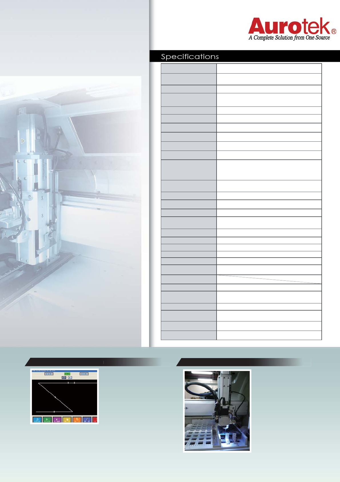
PATHWAY
SIMULATION
R
outing
B
it
S
ectioning
Pathway simulation function can
easily accurate understanding
of current cutting point or has
been cut point at any time. In
order to observe and modify,
reduce duplication sure that
each cut point time-consuming.
Routing bit automatically lift
and shift to next programmed
point then cutting to extend
the life time of routing bit.
藉由路徑模擬功能可以隨時準確地了
解目前未切割路徑及已切割路徑,以
便觀察與修改,減少重覆確認每個切
割點所耗費的時間。
銑刀切割一定距離後自動上升/下降
至另一段未切割之刀刃位置,以延
長銑刀壽命。
パスシミュレーション機能を通し、テ
ィーチングの確認時間を短縮すること
ができ、カットされた、またはカット
中のポイントの位置を確認できます。
ビットは基板切断後カットポジショ
ンを自動シフトし、ビットの消耗を
ビットの寿命を最大に活かします。
2
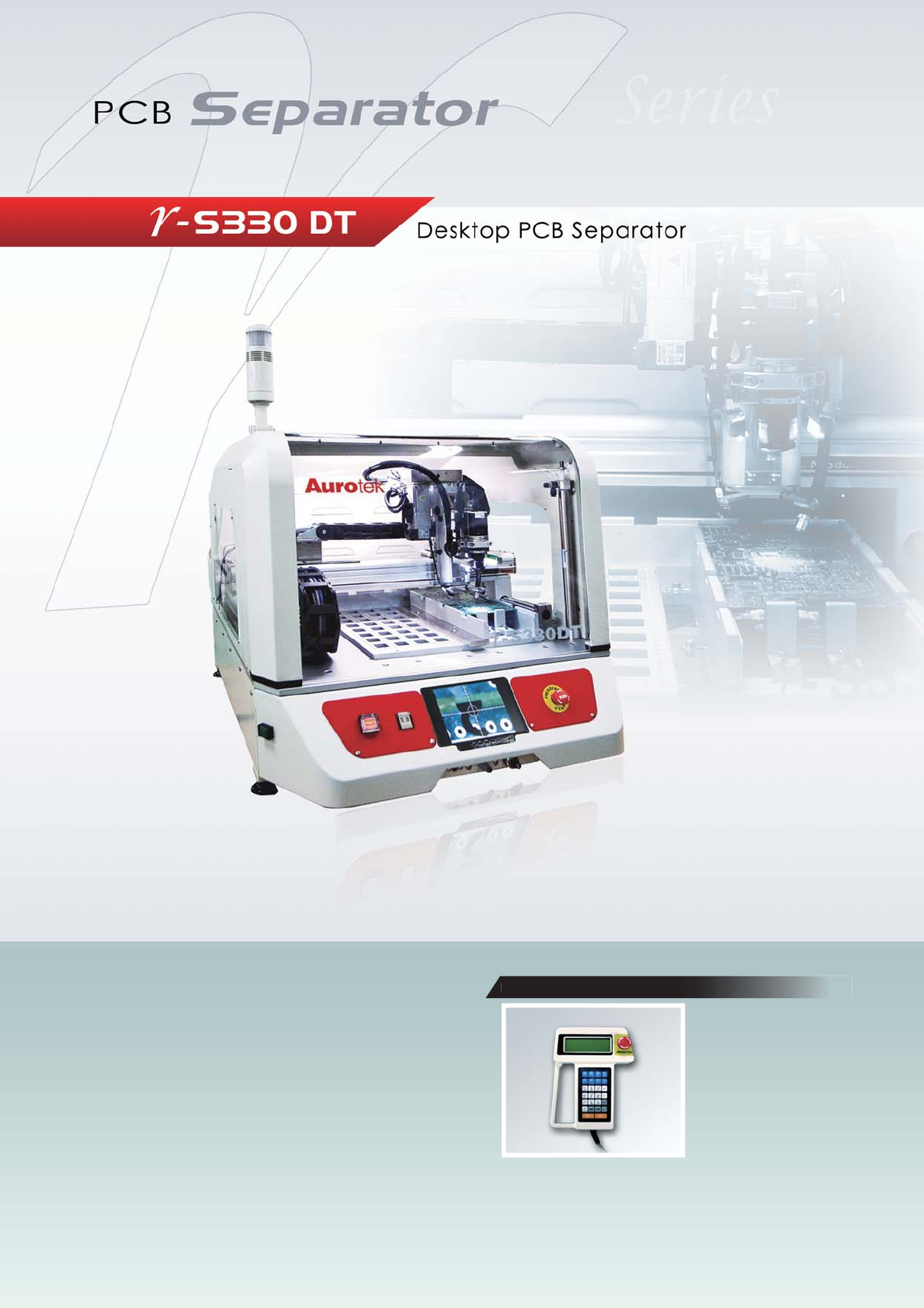
Suitable for Small Lot Production
T
eaching pad introducti
on
n
Teaching Pad Introduction
Help starter to operate the
separator easily. Feel free to
program and edit routing path
by teaching pad.
TP-104E操控器,操作介面簡單,
方便使用,能快速執行基板切割路徑
之程式製作以及編輯。
TP-104Eティーチングペンダントにより操作が簡易化。基盤分割パターンのセ
ッテイングや編集が自由自在。
3