00198609-01_AI_Replacing_the_X_and_Y_Trailing_Cable_EbS_EN.pdf - 第14页
2 Replacing the X trailing cable vacuum 2.1 Removal / Installation 14 Assembly Instructions E by SIPLACE Replacing the X and Y Trailing Cable 04/2018 2.1 Removal / Installation NOTICE Marking connections Before you unplu…
2 Replacing the X trailing cable vacuum
Assembly Instructions E by SIPLACE Replacing the X and Y Trailing Cable 04/2018 13
2 Replacing the X trailing cable vacuum
Parts, equipment and tools
●
GR X trailing cable vacuum assembly [03103949-xx]
●
Socket wrench or open-end wrench size 7
●
Allen key
●
Dosage tip for Loctite [03019481-xx]
●
Loctite 241 [02101037-xx]
●
Loctite 406 [03017821-xx]
●
Ethanol (Isopropanol – IPA can be used as an alternative)
●
Phillips screwdriver size 2
●
Torx key size TX 8
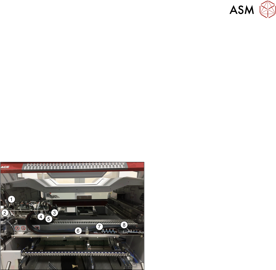
Overview
Fig.2: Overview
1. Cable to Vision board spread spectrum
and to the head interface
2. Vision board spread spectrum
3. Vacuum block
4. Top trailing cable fixture
5. Head interface
6. Bottom trailing cable fixture
7. Gantry interface X
8. Gantry interface
2 Replacing the X trailing cable vacuum
2.1 Removal / Installation
14 Assembly Instructions E by SIPLACE Replacing the X and Y Trailing Cable 04/2018
2.1 Removal / Installation
NOTICE
Marking connections
Before you unplug electrical or pneumatic connections, mark their positions clearly. So that
re-assemble back will be much easier.
► Switch off the machine, disconnect it from the power supply and secure it to prevent unauthor-
ized reactivation.
► Unplug all electrical connections from the trailing cable to the X gantry interface.
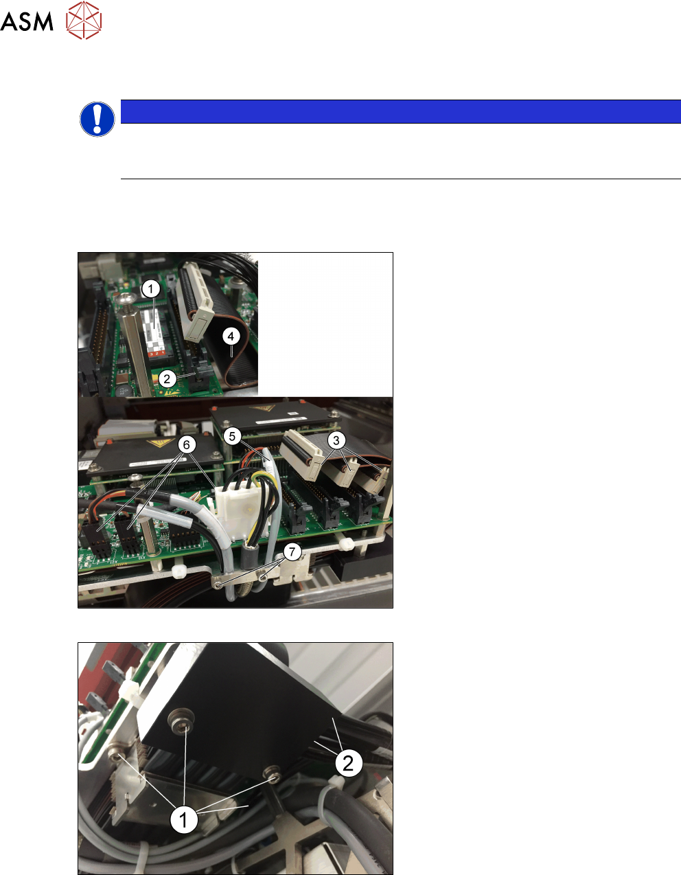
Fig.3: Unplugging electrical connections
► Unplug the electrical connections (3)
and (4) from the Vision board spread
spectrum (1) and from the head inter-
face (2).
► Unplug all electrical connections on the
head adapter to the solenoid (5) (one
plug) and to the X motor (6) (three
plugs).
► Loosen the fastening screws of the
cables (two screws M3x6 and one
hexagon bolt (7) to take out the cables
(Allen key size 2.5).
Fig.4: Vacuum block
► Carefully loosen the four screws (1)
(Allen key 3) fastening the vacuum
block and top trailing fixture.
► Disconnect the pneumatic hoses from
the vacuum block (2).
2 Replacing the X trailing cable vacuum
2.1 Removal / Installation
Assembly Instructions E by SIPLACE Replacing the X and Y Trailing Cable 04/2018 15
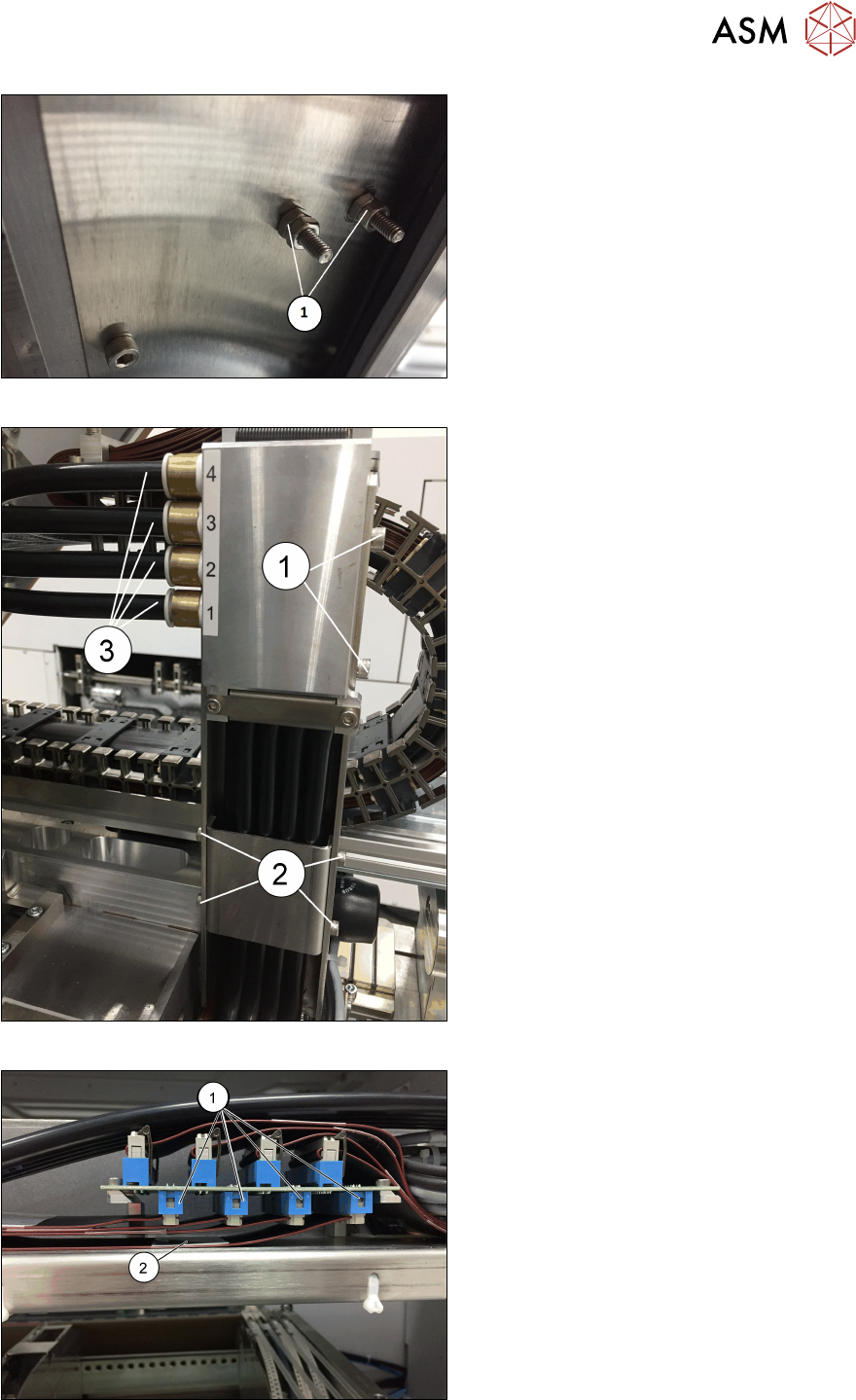
Fig.5: Top clamp on the trailing cable
► Loosen and remove the nuts and
hexagon bolts (1) (M4x10, size 7 mm)
for the top clamp on the trailing cable.
Fig.6: Disconnecting pneumatic hoses
► Carefully loosen the two screws (1)
(Allen key 4) and four screws (2) (Allen
key 3).
► Disconnect the four pneumatic
hoses(3).
Fig.7: Removing trailing cable and vacuum block
► Disconnect the four connectors(1).
► Remove the trailing cable(2) together
with metal vacuum block.