00198609-01_AI_Replacing_the_X_and_Y_Trailing_Cable_EbS_EN.pdf - 第18页
2 Replacing the X trailing cable vacuum 2.1 Removal / Installation 18 Assembly Instructions E by SIPLACE Replacing the X and Y Trailing Cable 04/2018 Fig.12: Securing individual hoses with Loctite 406 ► Repeat this proc…
2 Replacing the X trailing cable vacuum
2.1 Removal / Installation
Assembly Instructions E by SIPLACE Replacing the X and Y Trailing Cable 04/2018 17
CAUTION
Leaky connection
The four-fold air supply hose cannot be glued in place until the trailing cable and the distrib-
utor on the board holder have been assembled. Otherwise the connection could be dam-
aged and become leaky. For this reason, never open the hexagon bolts and the screws of
the vacuum connection in the top trailing cable if this is not absolutely necessary.
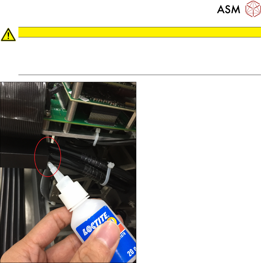
Fig.11: Secure with Loctite 406
The hoses of the trailing cable must be se-
cured with the thin fluid Loctite 406 instant
adhesive in the distributors.
► Use the dosage tip supplied.
► Make sure that a thin adhesive film is
laying around the hose.
► Apply the adhesive directly on the inter-
face between distributor and hose.
The adhesive is drawn into the gap between
hose and distributor by means of capillary
attraction.
2 Replacing the X trailing cable vacuum
2.1 Removal / Installation
18 Assembly Instructions E by SIPLACE Replacing the X and Y Trailing Cable 04/2018
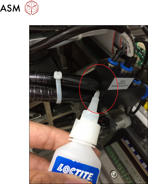
Fig.12: Securing individual hoses with Loctite 406
► Repeat this procedure for each indi-
vidual hose as well as for the four-fold
air supply hose from the trailing cable
into the vacuum connection.
► Reconnect the hoses for the head to the vacuum block.
► Reconnect all electrical connections of the trailing cable to the gantry interface X.
3 Replacing the Y trailing cable vacuum assembly
Assembly Instructions E by SIPLACE Replacing the X and Y Trailing Cable 04/2018 19
3 Replacing the Y trailing cable vacuum
assembly
Parts, equipment and tools
●
GR Y trailing cable vacuum assembly [03104723-xx]
Overview
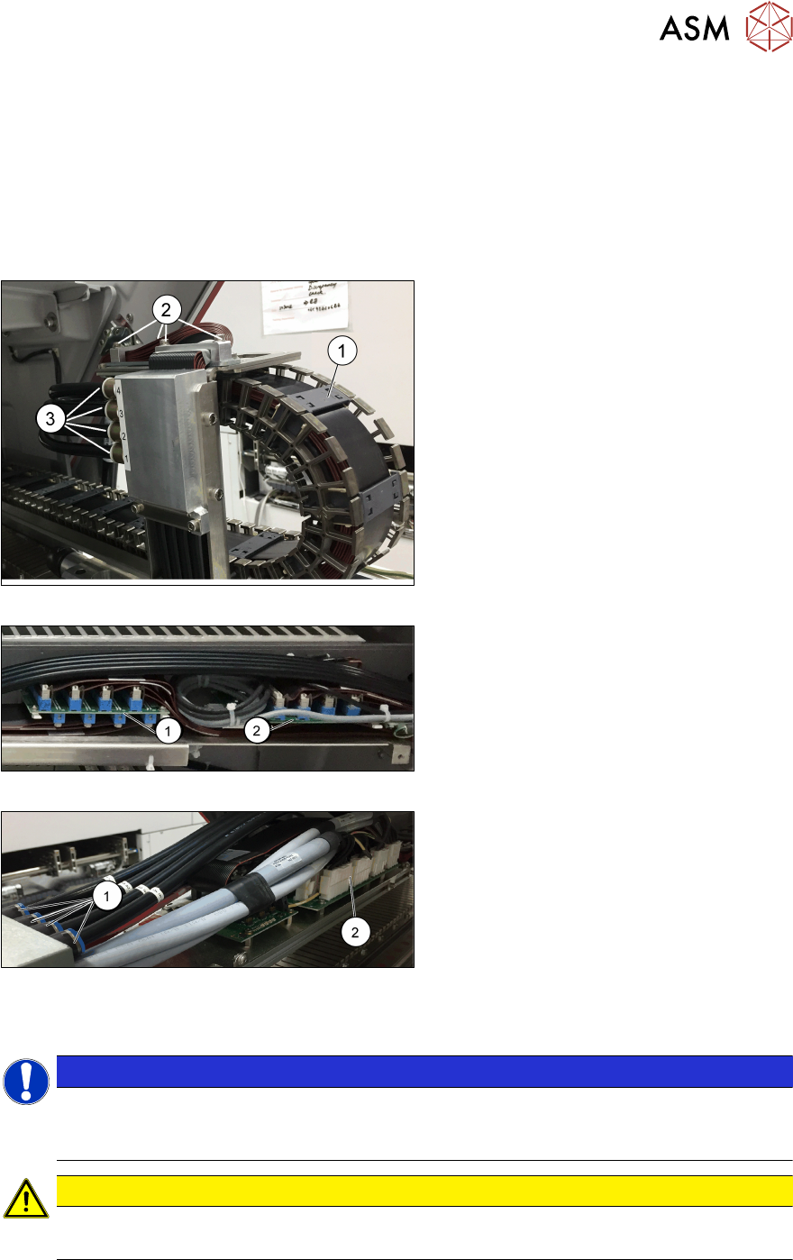
Fig.13: Trailing cable chain
1. Trailing cable chain
2. Screws fastening the trailing cable
chain to the gantry
3. Pneumatic hoses to the gantry
Fig.14: Gantry interfaces X and Y
1. Gantry interface X
2. Gantry interface Y
Fig.15: Valve joint and Trailing interface
1. Valve joint
2. Trailing interface
Removal
NOTICE
Marking the positions
Before you unplug electrical or pneumatic connections, mark their positions clearly. So that
re-assemble back will be much easier.
CAUTION
Cables and hoses
Make sure that the trailing cable chain, cable and hoses are not folded or damaged.
► Switch off the machine, disconnect it from the power supply and secure it to prevent unauthor-
ized reactivation.
► Remove the cover over the gantry interface on the X and Y axes.