00198609-01_AI_Replacing_the_X_and_Y_Trailing_Cable_EbS_EN.pdf - 第19页
3 Replacing the Y trailing cable vacuum assembly Assembly Instructions E by SIPLACE Replacing the X and Y Trailing Cable 04/2018 19 3 Replacing the Y trailing cable vacuum assembly Parts, equipment and tools ● GR Y tra…
2 Replacing the X trailing cable vacuum
2.1 Removal / Installation
18 Assembly Instructions E by SIPLACE Replacing the X and Y Trailing Cable 04/2018
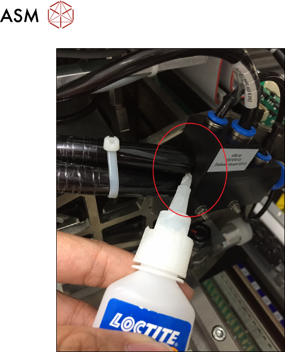
Fig.12: Securing individual hoses with Loctite 406
► Repeat this procedure for each indi-
vidual hose as well as for the four-fold
air supply hose from the trailing cable
into the vacuum connection.
► Reconnect the hoses for the head to the vacuum block.
► Reconnect all electrical connections of the trailing cable to the gantry interface X.
3 Replacing the Y trailing cable vacuum assembly
Assembly Instructions E by SIPLACE Replacing the X and Y Trailing Cable 04/2018 19
3 Replacing the Y trailing cable vacuum
assembly
Parts, equipment and tools
●
GR Y trailing cable vacuum assembly [03104723-xx]
Overview
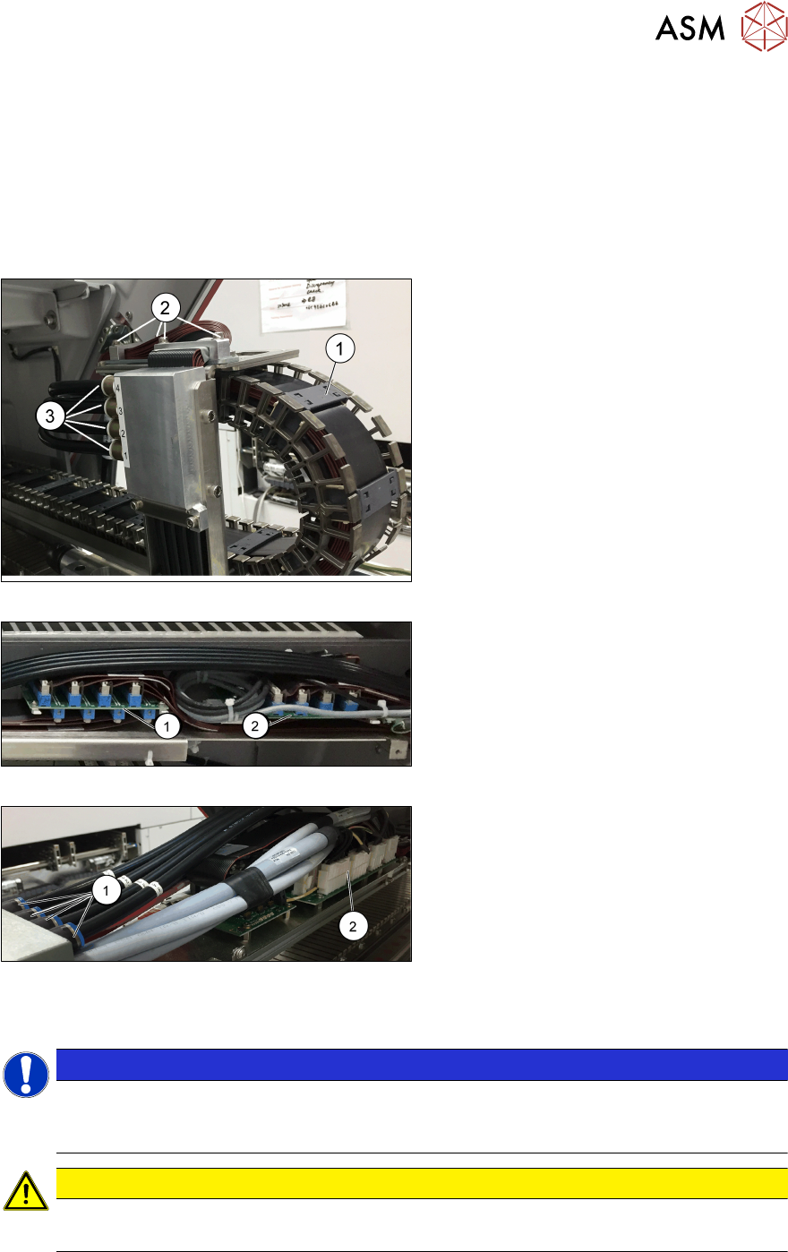
Fig.13: Trailing cable chain
1. Trailing cable chain
2. Screws fastening the trailing cable
chain to the gantry
3. Pneumatic hoses to the gantry
Fig.14: Gantry interfaces X and Y
1. Gantry interface X
2. Gantry interface Y
Fig.15: Valve joint and Trailing interface
1. Valve joint
2. Trailing interface
Removal
NOTICE
Marking the positions
Before you unplug electrical or pneumatic connections, mark their positions clearly. So that
re-assemble back will be much easier.
CAUTION
Cables and hoses
Make sure that the trailing cable chain, cable and hoses are not folded or damaged.
► Switch off the machine, disconnect it from the power supply and secure it to prevent unauthor-
ized reactivation.
► Remove the cover over the gantry interface on the X and Y axes.
3 Replacing the Y trailing cable vacuum assembly
20 Assembly Instructions E by SIPLACE Replacing the X and Y Trailing Cable 04/2018
► Unplug all pneumatic connections to the gantry.
► Unplug all electrical connections from the trailing cable to the X and Y trailing cable interface.
► Unplug all pneumatic connections to the valve joint.
► Unplug the electrical connections to the trailing cable interface.
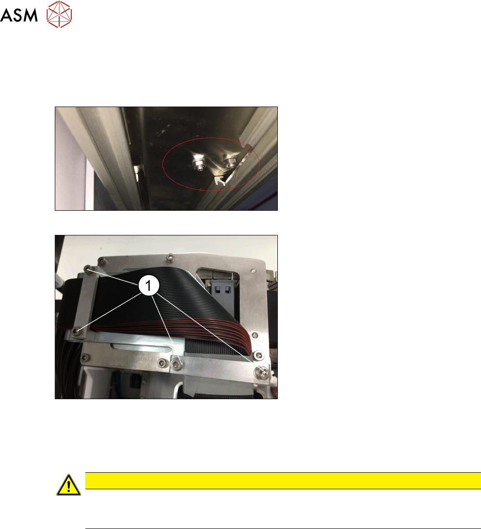
Fig.16: Bracket on top of trailing cable
► Loosen the two screws and nuts
fastening the trailing cable chain to the
gantry. These screws (hexagonal bolts
[03023606-xx]) must be resealed with
Loctite 241 when fitted again.
Fig.17: Removing trailing cable
► Loosen the four screws fastening the
bracket (1) on the top of trailing cable.
► Remove the trailing cable from the
machine.
Installation
► Follow the removal instructions in reverse order for installation. Also observe the following
instructions:
CAUTION
Installation instructions
Fix the screws fastening the trailing cable chain to the gantry and to the cover with Loctite
241.