Infinity EX Print Carriage Module.pdf - 第4页
INFINITY EX PRINT CARRIAGE M ODULE MECHANICAL DETA IL 9.4 Technical Reference Manu al Chapter Issue 2 Aug 02 MECHANICAL DET AIL Print Carriage The main construction of the print carriage is mac hine cast for ligh tness a…
INFINITY
EX
PRINT CARRIAGE MODULE
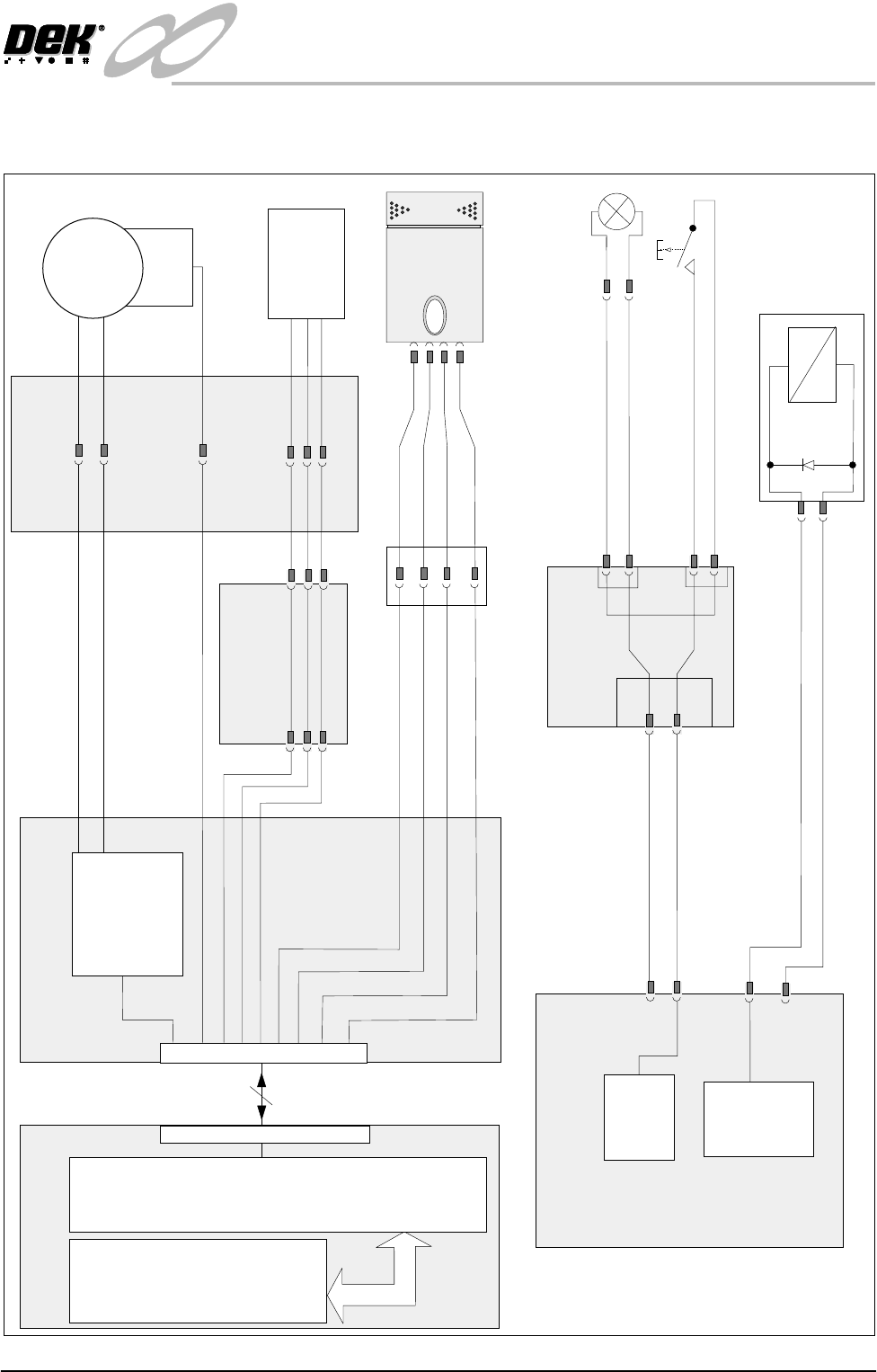
ELECTRICAL SCHEMATIC
Chapter Issue 2 Aug 02 Technical Reference Manual 9.3
ELECTRICAL SCHEMATIC
Machine Controller
+12v USR
Breakout Board A
+
M
Temperature/Humidity
Sensor (9SE20)
Servo Drive
T
H
APL1
ASK6
Servo 1 Motor +ve
Servo 1 Motor -ve
ADC2
Analog gnd
ADC 4
ye
gn
bu
rd
+12v USR
Machine PC
100 Way
Processor
ISA Bus
NextMove
9SK57
Encoder
(9EN1)
Servo
Motor
(9M2)
Machine Print
Head
9PL37
9SK37
8SK32 8PL32
Print Carriage
Home
9SE3
9SK14
9PL14
8SK32
DigIN6
0v USR
Pin 1
Pin 2
Pin 3
9SK43
9PL43
Breakout Board C
Paste Roll Lamp
(9LP1)
24V (u/s)
CPL8
CPL10
CSK8
CSK10
0v
CSK3
Pin 1
Pin 2
9SK55/9PL55
Paste Roll
Lamp Switch
(8SW4)
Pin 2
Pin 1
CPL3
M24 DC Power Supply Module
Print Carriage
Brake Solenoid
(9SOL03)
9SK36
24V (sw)
0v
Contactor
#2
+24V
M24PL08
M24PL09
1
2
B
A
A
B
X9
INFINITY
EX
PRINT CARRIAGE MODULE
MECHANICAL DETAIL
9.4 Technical Reference Manual Chapter Issue 2 Aug 02
MECHANICAL DETAIL
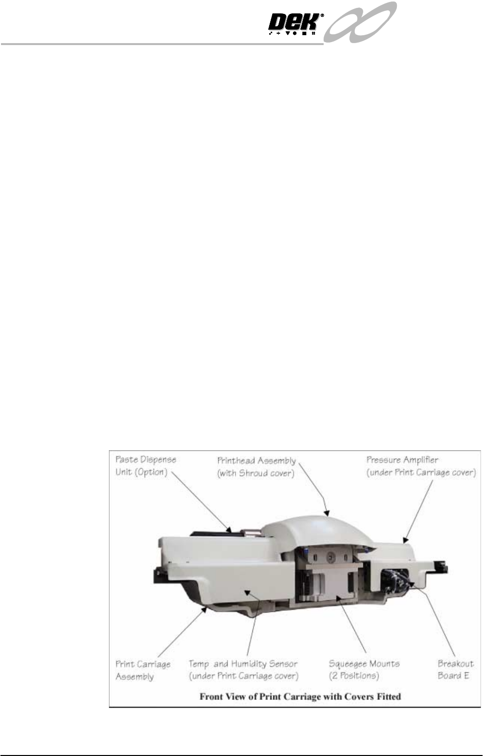
Print Carriage The main construction of the print carriage is machine cast for lightness and
strength. The following units are housed on the print carriage:
• Printhead Assembly
• Pressure Amplifier Unit
• Temperature and Humidity Sensor
• Paste Dispense mechanism (optional)
• Breakout Board E
NOTE
1. Information on the printhead assembly and pressure amplifier unit is
detailed in the Squeegee chapter of this manual.
2. Temperature and humidity sensor information is detailed in the Drives and
Sensors section of this chapter.
3. Information on the paste dispense mechanism is detailed in the Paste Dis-
pense chapter of this manual.
4. Information on breakout board E is detailed in the Machine Controller
chapter of this manual.
The print carriage is mounted on two guide rails enabling the unit to traverse in
the Y direction over the screen. Movement is achieved by utilizing a servo
motor, timing belt and pulley system. The right hand side print carriage is
secured by a timing belt by means of a belt clamp. All cabling from the print
carriage to the machine is contained within the drag chain sited on the right hand
side of the timing belt and pulley system.
Figure 9-2 Print Carriage Assembly (Front View)
INFINITY
EX
PRINT CARRIAGE MODULE
MECHANICAL DETAIL
Chapter Issue 2 Aug 02 Technical Reference Manual 9.5
Print Carriage
Motor
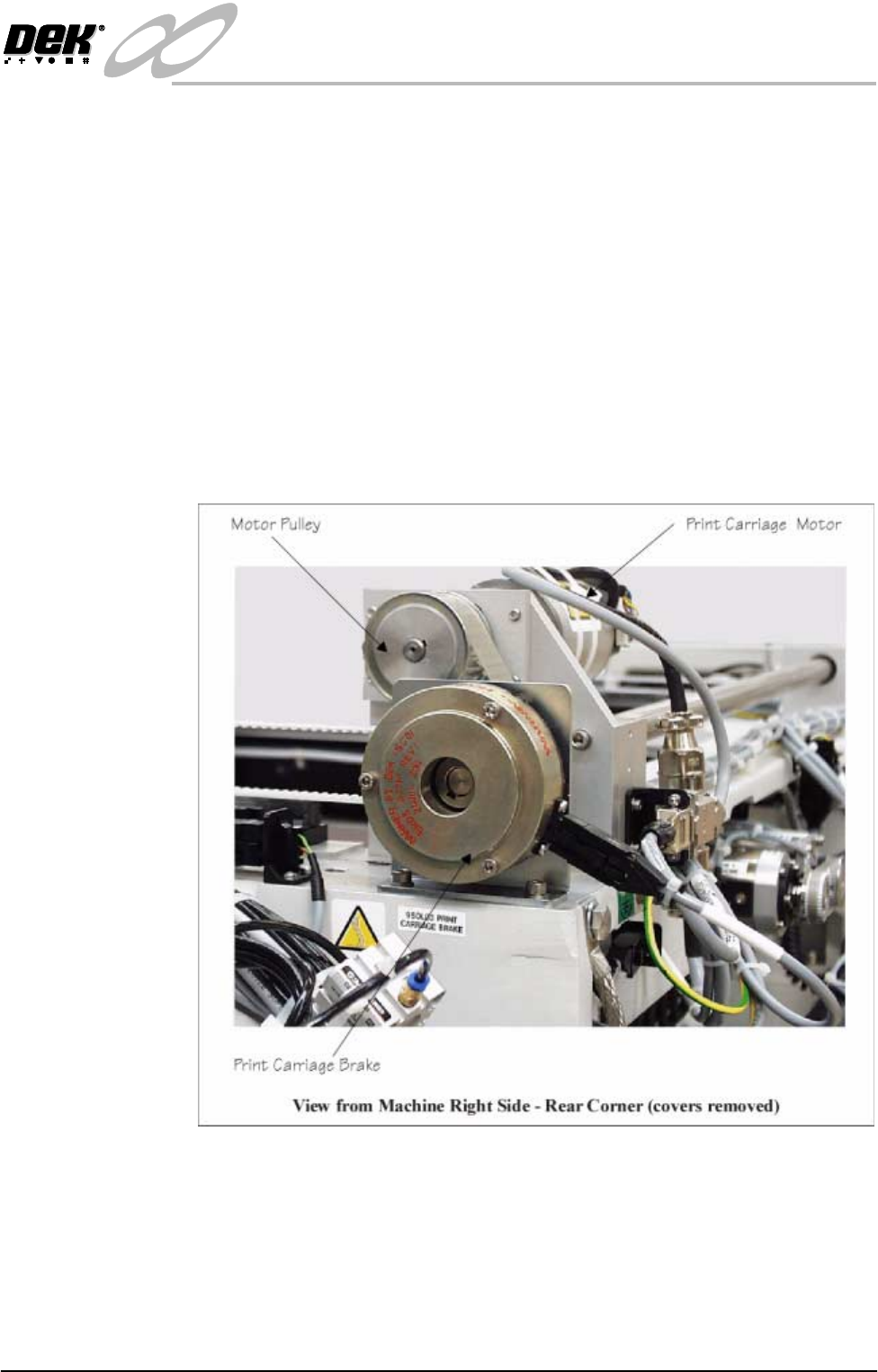
The print carriage motor is a dc servo type motor with integral gearbox and
encoder. This motor is fitted at the rear right hand corner of the print carriage
rail system.
NOTE
Further information on servo motors is detailed in the Sensors and Motors
chapter of this manual.
Brake When the machine system power is cut, power is removed from the print carriage
motor. Without power the motor is unable to maintain the position of the print
carriage thus creating a potential hazard when the head is raised. To prevent
inadvertent print carriage movement when the machine power is cut, an electro-
magnetic brake is fitted to the print carriage drive pulley.
The brake is only released when system power is enabled and 24V is supplied
to the brakes electromagnetic coil via No.2 Contactor of the M24 dc power
supply module.
Figure 9-3 Print Carriage Brake
Temperature and
Humidity Sensor
The optional temperature and humidity sensor provides the operator with tem-
perature and humidity information for the printhead area of the machine. Further
information on the sensor is detailed in the Drives and Sensors section of this
chapter.