Infinity EX Print Carriage Module.pdf - 第8页
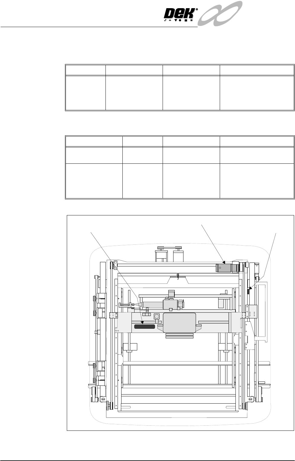
INFINITY EX PRINT CARRIAGE M ODULE DRIVE S AND SE NSOR S 9.8 Technical Reference Manu al Chapter Issue 2 Aug 02 DRIVES AND SENSORS Motors Senso rs Figur e 9-5 Drives and Sensors Name T ype Control Card Functional Descrip…

INFINITY
EX
PRINT CARRIAGE MODULE
MECHANICAL DETAIL
Chapter Issue 2 Aug 02 Technical Reference Manual 9.7
Guide Rails The print carriage assembly is traversed across the screen via two linear guide
rails. Both guide rails are fixed in position to the machine printhead casting.
Carriage Rails The print carriage rails are a linear bearing type rail onto which the print carriage
is secured.
Print Carriage
Motor
The print carriage motor is a dc servo type motor with integral gearbox and
encoder. This motor is fitted at the rear right hand corner of the print carriage
rail system. The print carriage is driven through a pulley and timing belt system
located on the right hand side of the machine, (Drives and Sensors figure of this
chapter refers).
NOTE
Technical information on servo motors is detailed in the Sensors and Motors
chapter of this manual.
INFINITY
EX
PRINT CARRIAGE MODULE
DRIVES AND SENSORS
9.8 Technical Reference Manual Chapter Issue 2 Aug 02
DRIVES AND SENSORS
Motors
Sensors
Figure 9-5 Drives and Sensors
Name Type Control Card Functional Description
Print Carriage
Motor
Servo Motor with
Gearbox (50:1) and
Encoder
Machine Controller
Servo Drive Card
Drives the print carriage
along the Y axis.
Provides feedback of the
print carriage position via an
integral encoder
Name Type Control Card Functional Description
Print Carriage Home Hall Effect NextMove DIG IN 6 Determines the home posi-
tion of the print carriage
Temperature &
Humidity (Optional)
Temp - NTC
resistive
Hum - Capac-
tive
NextMove
Temp - ADC2
0V - Analog gnd
Hum - ADC4
+12V - USR
Produces temperature and
Humidity information from
the printhead area of the
machine
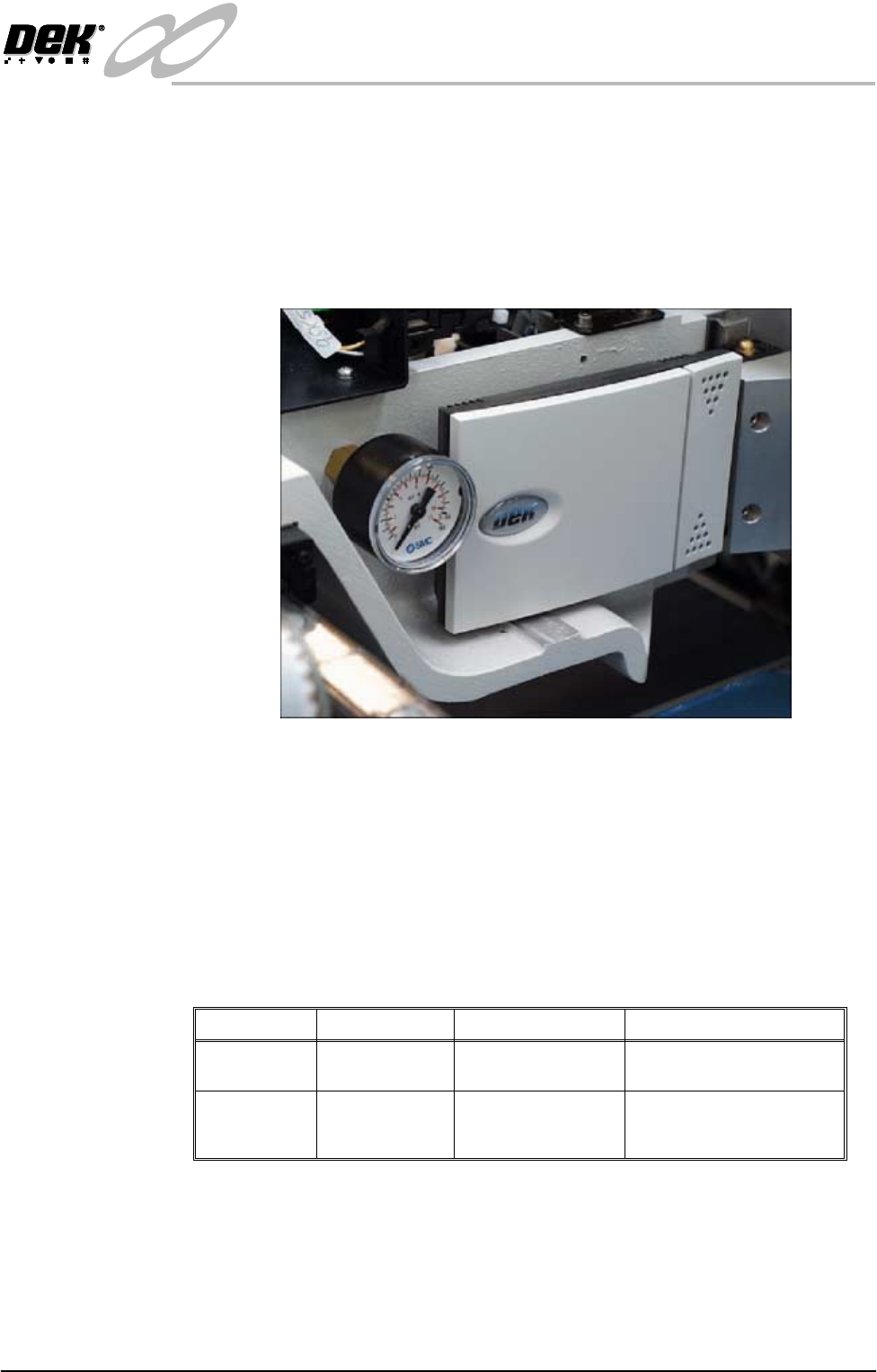
Temperature and
Humidity Sensor
Print Carriage Motor Print Carriage
Home Sensor
INFINITY
EX
PRINT CARRIAGE MODULE
DRIVES AND SENSORS
Chapter Issue 2 Aug 02 Technical Reference Manual 9.9
Temperature and
Humidity Sensor
The temperature and humidity sensor option is utilized during the applications
process of printing. In order to achieve maximum print quality during the
printing process, a continuous temperature and humidity monitor of the machine
printhead area is required.
The sensor provides the operator with accurate real time information of the
internal temperature and humidity levels of the machine. This is displayed on
the machine monitor Printer - Status window.
Figure 9-6 Temperature and Humidity Sensor
The sensor is a 4 wire transmitter which measures relative humidity, utilizing a
capacitive sensor, and temperature with an NTC resistive type sensor. Essen-
tially the sensor behaves like a variable source of current or voltage that is
adjusted dependent upon the temperature and humidity conditions.
Two linearized output signals are read by the machine PC NextMove card
(Temperature - ADC2 / Humidity - ADC4). Real time information is displayed
on the machine monitor Status Window.
The parameters of the temperature and humidity sensor is:
NOTE
Information on the application process of printing is detailed in the Print Quality
chapter of this manual.
Range Time Constant Accuracy
Temperature 5°C - 45°C 180 secs (still air) ±0.25°C at 25°C
±0.5°C from 0° - 50°C
Humidity 10%rH - 90%rH 15 secs (still air) 10 - 90%rH
±3% at 25°C
±6% from 0° - 50°C