Infinity EX Print Carriage Module.pdf - 第6页
INFINITY EX PRINT CARRIAGE M ODULE MECHANICAL DETA IL 9.6 Technical Reference Manu al Chapter Issue 2 Aug 02 Paste Dispenser Mechanism O ption The paste di spenser option is only util ized when the m achine is f itt ed w…
INFINITY
EX
PRINT CARRIAGE MODULE
MECHANICAL DETAIL
Chapter Issue 2 Aug 02 Technical Reference Manual 9.5
Print Carriage
Motor
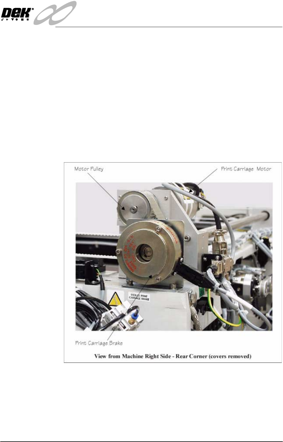
The print carriage motor is a dc servo type motor with integral gearbox and
encoder. This motor is fitted at the rear right hand corner of the print carriage
rail system.
NOTE
Further information on servo motors is detailed in the Sensors and Motors
chapter of this manual.
Brake When the machine system power is cut, power is removed from the print carriage
motor. Without power the motor is unable to maintain the position of the print
carriage thus creating a potential hazard when the head is raised. To prevent
inadvertent print carriage movement when the machine power is cut, an electro-
magnetic brake is fitted to the print carriage drive pulley.
The brake is only released when system power is enabled and 24V is supplied
to the brakes electromagnetic coil via No.2 Contactor of the M24 dc power
supply module.
Figure 9-3 Print Carriage Brake
Temperature and
Humidity Sensor
The optional temperature and humidity sensor provides the operator with tem-
perature and humidity information for the printhead area of the machine. Further
information on the sensor is detailed in the Drives and Sensors section of this
chapter.
INFINITY
EX
PRINT CARRIAGE MODULE
MECHANICAL DETAIL
9.6 Technical Reference Manual Chapter Issue 2 Aug 02
Paste Dispenser
Mechanism Option
The paste dispenser option is only utilized when the machine is fitted with
squeegees, and provides an automated paste dispensing facility during print
operations. Further information is detailed in the Paste Dispenser System
chapter of this manual.
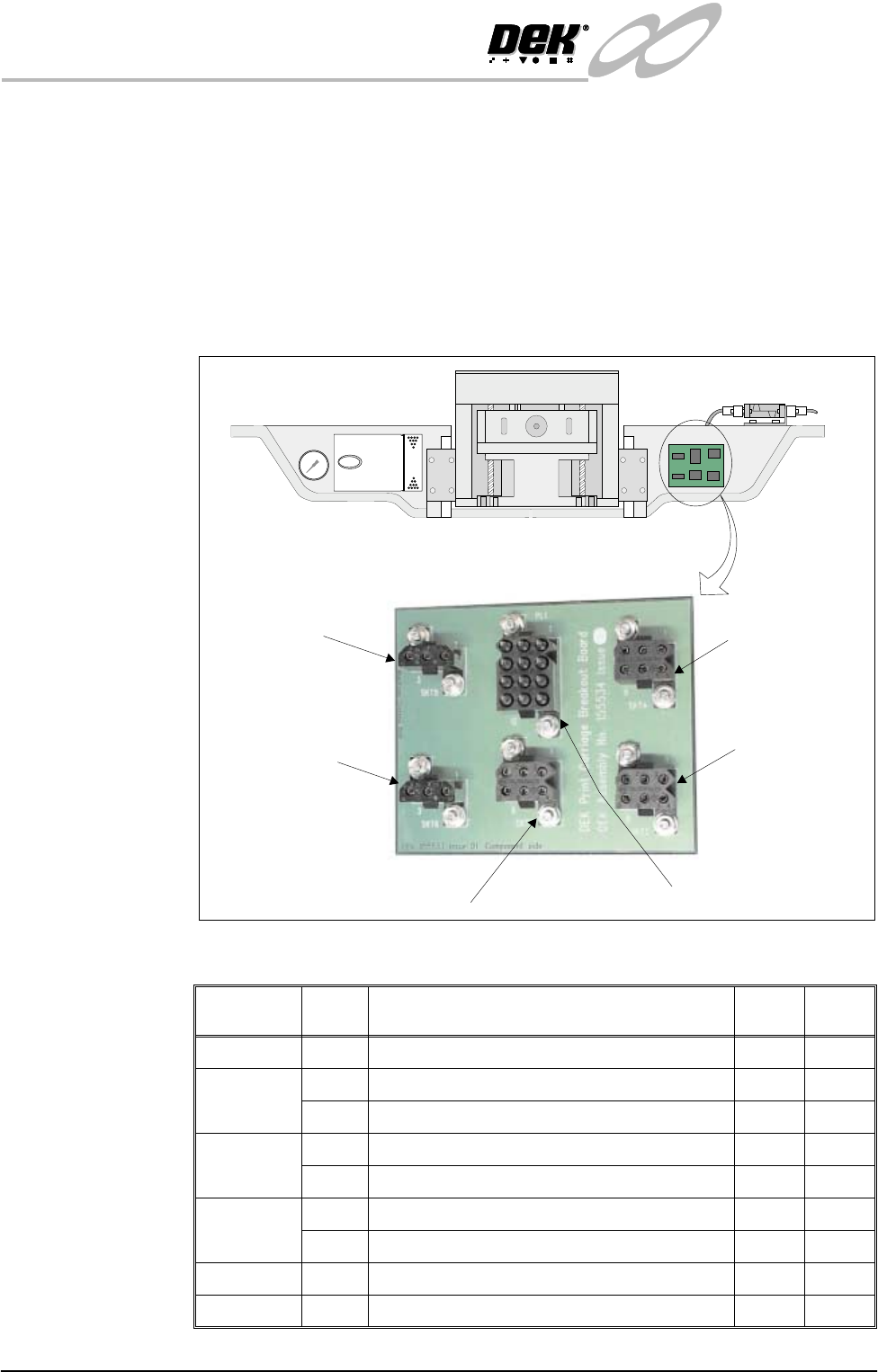
Breakout Board E The PCB breakout board E is the signal interface between the machine controller
and assemblies fitted to the print carriage. Socket descriptions are detailed in
the table below. Further information on each assembly can be found in the
relevant module chapter of this manual.
Figure 9-4 Breakout Board E
Socket/Plug
No.
Pin
No.
Description +12V
Pins
0V
Pins
EPL1 Input Signals from Machine Controller 1 ; 2 3 ; 12
ESK2 5 ProFlow Cassette Low 1 3
2 ProFlow Fitted 4 6
ESK3 5 Cartridge Horizontal 4 6
2 Cartridge Vertical 1 3
ESK4 2 Front Squeegee Home 1 3
5 Rear Squeegee Home / ProFlow Home 4 6
ESK5 2 Paste Carriage Home 1 3
ESK6 2 Cartridge Empty 1 3
Socket 4
(Squeegee/ProFlow
Home Sensors)
Socket 2
(ProFlow Fitted/
Paste Low Sensor)
Plug 1 (Machine Controller Input Signals)Socket 3 (Paste Cartridge Sensor)
Socket 5
(Paste Carriage
Home)
Socket 6
(Paste Cartridge
Empty)

INFINITY
EX
PRINT CARRIAGE MODULE
MECHANICAL DETAIL
Chapter Issue 2 Aug 02 Technical Reference Manual 9.7
Guide Rails The print carriage assembly is traversed across the screen via two linear guide
rails. Both guide rails are fixed in position to the machine printhead casting.
Carriage Rails The print carriage rails are a linear bearing type rail onto which the print carriage
is secured.
Print Carriage
Motor
The print carriage motor is a dc servo type motor with integral gearbox and
encoder. This motor is fitted at the rear right hand corner of the print carriage
rail system. The print carriage is driven through a pulley and timing belt system
located on the right hand side of the machine, (Drives and Sensors figure of this
chapter refers).
NOTE
Technical information on servo motors is detailed in the Sensors and Motors
chapter of this manual.