OM-1076-001.pdf - 第126页
B02 Recognition Data (B02_10) 0206-003 2-95 Tg0502-PM-CL Fig. B203 Enable (Auto) 0.00 Lead posn (latl dir) detn Lead posn (latl dir) tol [mm] (B02_10) Lead Posn (Latl Dir) Detn/Lead Posn (Latl Dir) T ol [mm] Select wheth…
(B02_09) Lead Width Detn/Lead Width Tol [mm]
Select whether or not the Lead Width Judgement is performed. If it is,
select the allowance from the following options.
Disable : Select this when the lead width determination
should not be made.
Enable (Auto) : Select this to automatically set the lead width toler-
ance according to the dimensional data of the leads.
Enable (Mnl) : Select this to arbitrarily set the lead width tolerance.
Unit: mm
Data Input Range: 0 to 9.99
(a) Set this only when "Manual" is set in the "Recognition data set" text
box.
(b) When "Enable (Auto)" is set in the "Lead width detn" text box, the
value indicated in the "Lead width tol [mm]" text box is used.
Applicable Components : IC (Simple), IC (Complex), Other
Leaded (Simple), and Other Leaded
(Complex)
0206-003 2-94
Tg0502-PM-CL
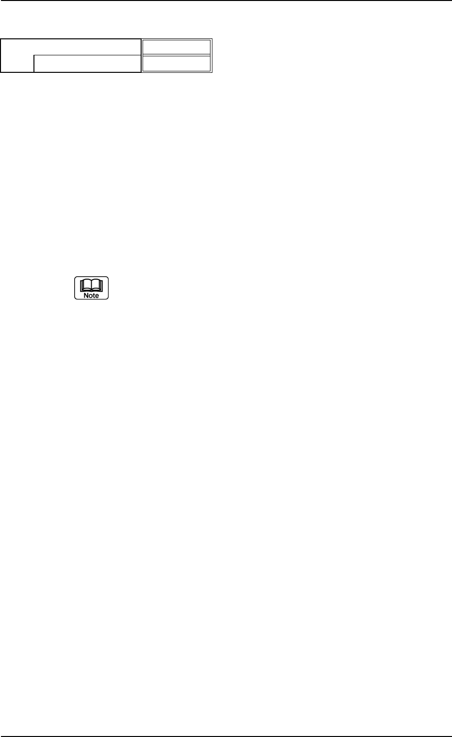
B02 Recognition Data (B02_09)
Fig. B202
Enable (Mnl)
0.30
Lead width detn
Lead width tol [mm]
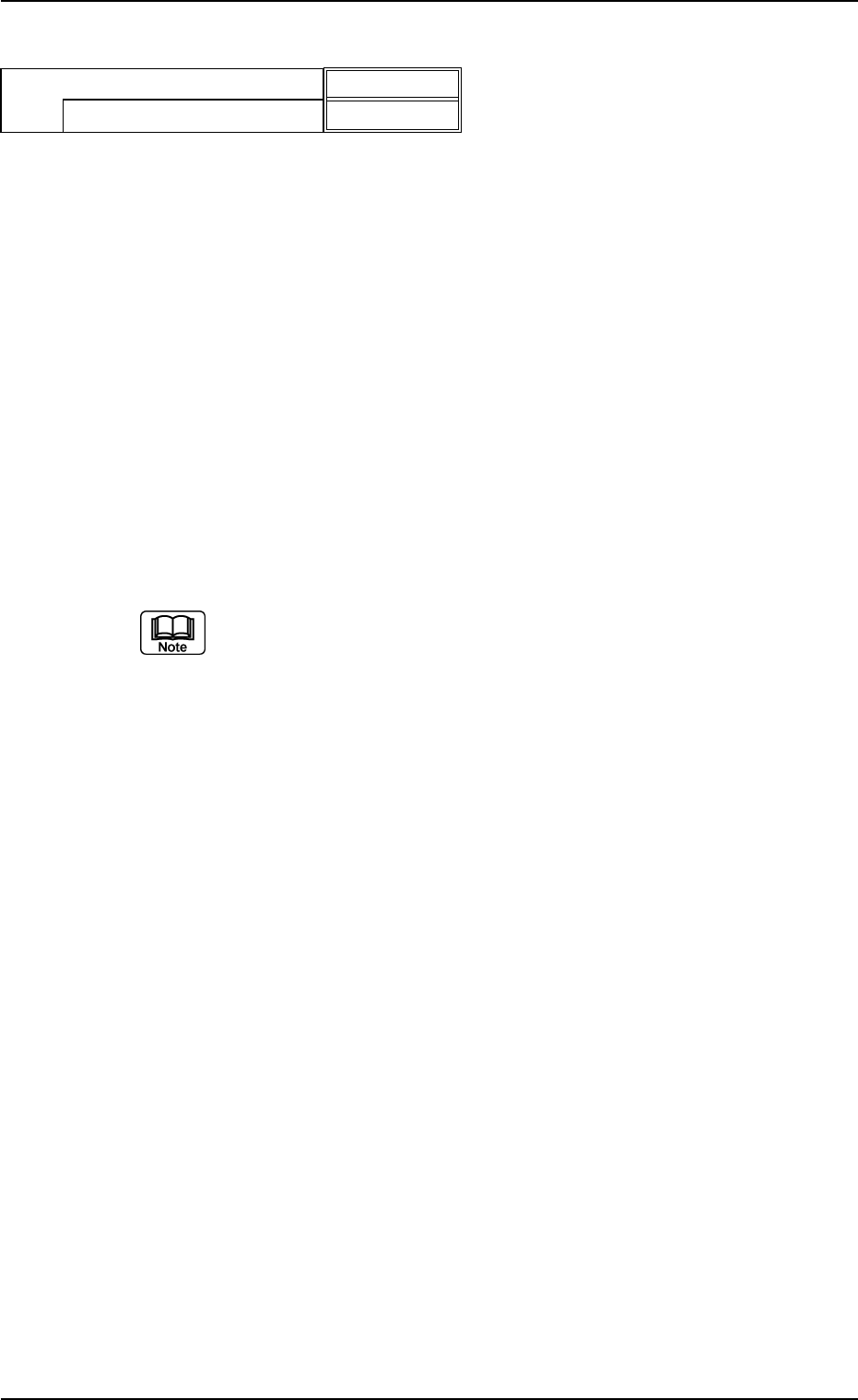
B02 Recognition Data (B02_10)
0206-003 2-95 Tg0502-PM-CL
Fig. B203
Enable (Auto)
0.00
Lead posn (latl dir) detn
Lead posn (latl dir) tol [mm]
(B02_10) Lead Posn (Latl Dir) Detn/Lead Posn (Latl Dir) Tol [mm]
Select whether or not the Lead Position Judgement to the lead width
direction is performed. If it is, select the allowance from the following
options.
Disable : Select this when the lead position (lateral direc-
tion) should not be detected.
Enable (Auto) : Select this to automatically set the lead position
(lateral direction) tolerance according to the dimen-
sional data of the leads.
Enable (Mnl) : Select this to arbitrarily set the lead position (lat-
eral direction) tolerance.
Unit: mm
Data Input Range: 0 to 9.99
(a) Select this only when "Manual" is set in the "Recognition data set" text
box.
(b) When "Enable (Auto)" is set in the "Lead posn (latl dir) detn" text box,
the value indicated in the "Lead posn (latl dir) tol [mm]" text box is
used.
Applicable Components : IC (Simple), IC (Complex), Connector
(Simple), Connector (Complex), Other
Leaded (Simple), and Other Leaded
(Complex)
0206-003 2-96 Tg0502-PM-CL
B02 Recognition Data (B02_12)
(B02_12) Outward length detn/Outward length tol [mm]
Select one of the following options to determine whether or not the
positional deviation of the lead group end line should be determined.
When "Enable (Auto)" or "Enable (Mnl)" is selected, the tolerance
must be specified.
Disable : Select this when the outward length should not be
determined.
Enable (Auto) : Select this to determine the outward length auto-
matically.
When this is selected, the default (automatically
specified value) is used.
Enable (Mnl) : Select this to determine the outward length manu-
ally.
The manually specified value is used as an out-
ward length tolerance.
Unit: mm
Data Input Range: 0 to 9.99
(a) To set a parameter, select "Manual" in the "Recog data set" text box.
(b) When "Enable (Auto)" is set in the "Outward length detn" text box, the
value indicated in the "Outward length tol [mm]" text box is used.
(c) As for ICs, it is required to set a parameter when "Gull Wing" or
"Straight" is selected in the "Type" text box of the label "Lead" in the
"Lead Data" tab sheet.
Applicable Components: Deform (Complex), IC (Simple), IC (Complex)
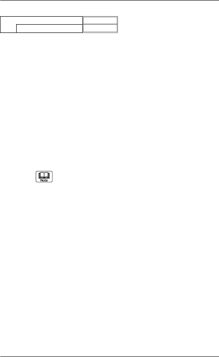
Fig. B204
Disable
0.00
Outward length detn
Outward length Tol [mm]