OM-1076-001.pdf - 第135页
(5) Inspection range image Select the brightness within the inspection range from the follow- ing options. Bright : Select when the specified range is brighter than the other inspection ranges. Dark : Select when the spe…
0206-001 2-103 Tg0502-PM-CL
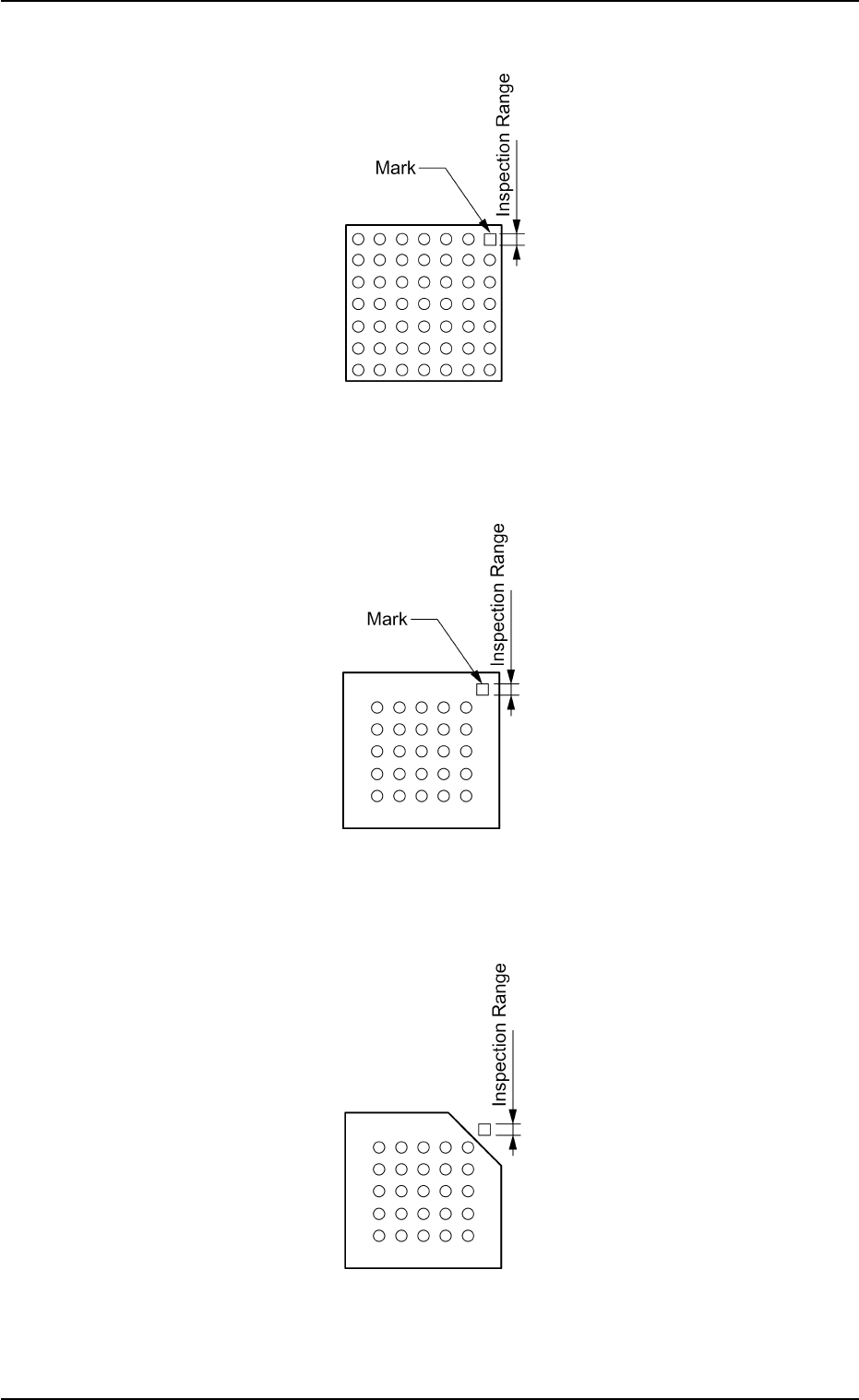
Example: Regarding the missing ball as a polarity
Top View of Component
Fig. B222
Example: Regarding the mark on the mold as a polarity
Top View of Component
Fig. B223
Example: Regarding the cutout of the mold as a polarity
Top View of Component
Fig. B224
B02 Recognition Data (B02_16)
(5) Inspection range image
Select the brightness within the inspection range from the follow-
ing options.
Bright : Select when the specified range is brighter than the other
inspection ranges.
Dark : Select when the specified range is darker than the other
inspection ranges.
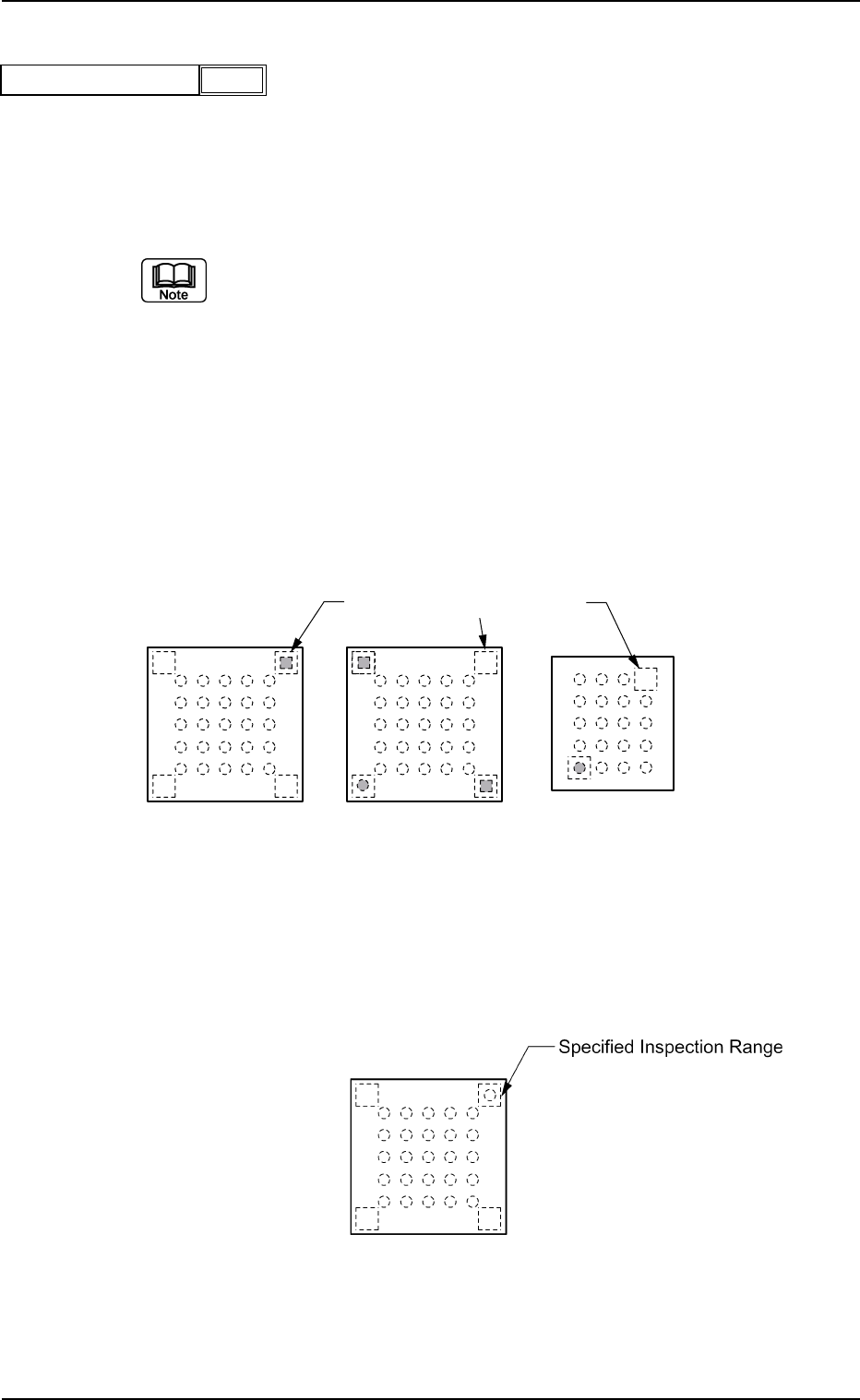
(a) When this data is set, set "Enable (Discard)" or "Enable (Placement)"
in the "Polarity detn" text box.
(b) In polarity determination, the polarity of the mold is determined ac-
cording to the brightness of the specified inspection range. There-
fore, select the inspection range that is clearly brighter or darker than
those in the other inspection ranges.
Example of Prominent Difference:
The system can determine whether or not components have a po-
larity because the difference in brightness is prominent between the
specified inspection range and the others.
Top View of Component
Fig. B226
Example of No Difference:
The system cannot determine whether or not the component has a
polarity because there is no difference in brightness between the
specified inspection range and the others.
Top View of Component
Fig. B227
0206-001 2-104
Tg0502-PM-CL
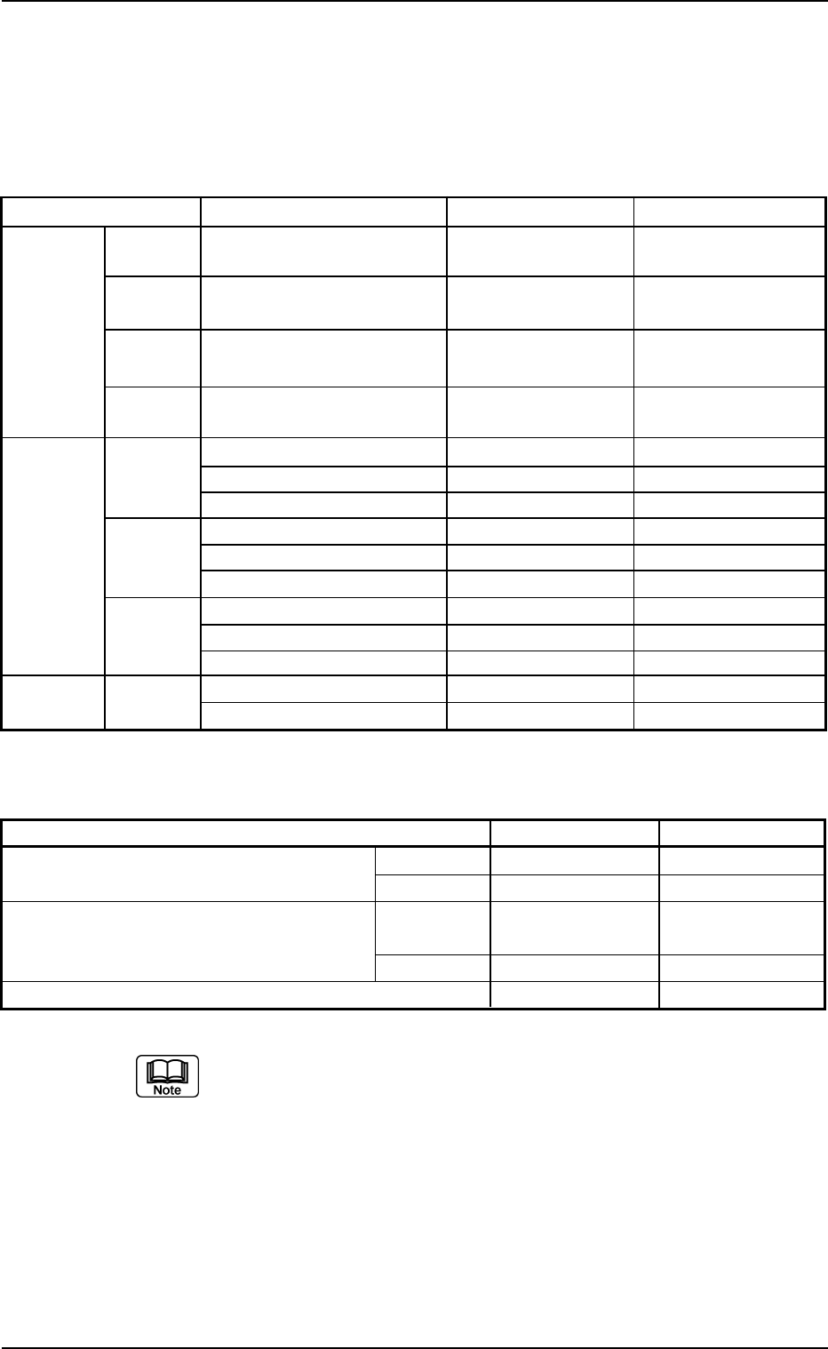
Bright
Fig. B225
Inspection range image
Specified Inspection Ranges
B02 Recognition Data (B02_16)
3. Max. and Min. Sizes by View Range
The maximum and Minimum sizes by view range are shown in the
following table.
Minimum Size by View Range
Component Shapes Item Small View Large View
Leadless Cyindrical Minimum Mold Size (mm) Long Side 1.0
×
Short Long Side 2.0
×
Short
Component
Side 0.5 Side 1.2
Square Minimum Mold Size (mm) Long Side 1.0
×
Short Long Side 2.0
×
Short
Side 0.5 Side 1.2
Deform Minimum Mold Size (mm) Long Side 1.0
×
Short Long Side 2.0
×
Short
(Simple) Side 0.5 Side 1.2
Deform Minimum Linear Edge Width
1.60 3.00
(Complex)
(mm)
Leaded IC Minimum Lead Width (mm) 0.10 0.18
Component
Minimum Lead Length (mm) 0.17 0.30
Minimum Lead Pitch (mm) 0.20 0.40
Connector Minimum Lead Width (mm) 0.10 0.18
Minimum Lead Length (mm) 0.17 0.30
Minimum Lead Pitch (mm) 0.20 0.40
Other Minimum Lead Width (mm) 0.17 0.30
Minimum Lead Length (mm) 0.17 0.30
Minimum Lead Pitch (mm) 0.20 0.40
Area Array BGA/CSP Minimum Ball Diameter (mm) 0.20 0.40
Minimum Ball Pitch (mm) 0.30 0.55
(a) For small view range, the maximum component size obtained is based
on the outline size, pick-up position correction, and component sup-
plying direction. For large view range (back lighting), it is based on the
range necessary for the recognition and pick-up position correction.
For large view range (front lighting), it is based on the range neces-
sary for the recognition and component supplying direction.
(b) The component shapes applicable for dividing view are deform (com-
plex), IC, connector and BGA/CSP.
(c) For components with outside dimensions of 10
×
10 mm or less, the
maximum component thickness is 6.5 mm.
Maximum Size by View Range
Item Small View Large View
Max. Component Size for Total View (mm) Front Ltg 24
×
18 46
×
34
Note (a) Back Ltg 18
×
18 18
×
18
Max. Component Size for Divided View (mm) Front Ltg 55
×
55
(or 100
×
26)
Note (b) Back Ltg
Max. Component Thickness (mm) 5 Note (c) 20
0206-001 2-105 Tg0502-PM-CL
3. Max. and Min. Sizes by View Range
Table B24
Table B23