TF36074_Chip Vacuum Check.pdf - 第5页
2nd SMT Engineering Division Softw are Gro up IM Operations Y AMAHA MOTOR CO., L TD MD OC-SOFT50395 5/11 3.3 Timing to output errors Between “after ca me ra r ecognition of picked parts” and “befor e mounting”, …
2nd SMT Engineering Division Software Group
IM Operations
YAMAHA MOTOR CO., LTD
MDOC-SOFT50395
4/11
3. Function overview
3.1 Outline
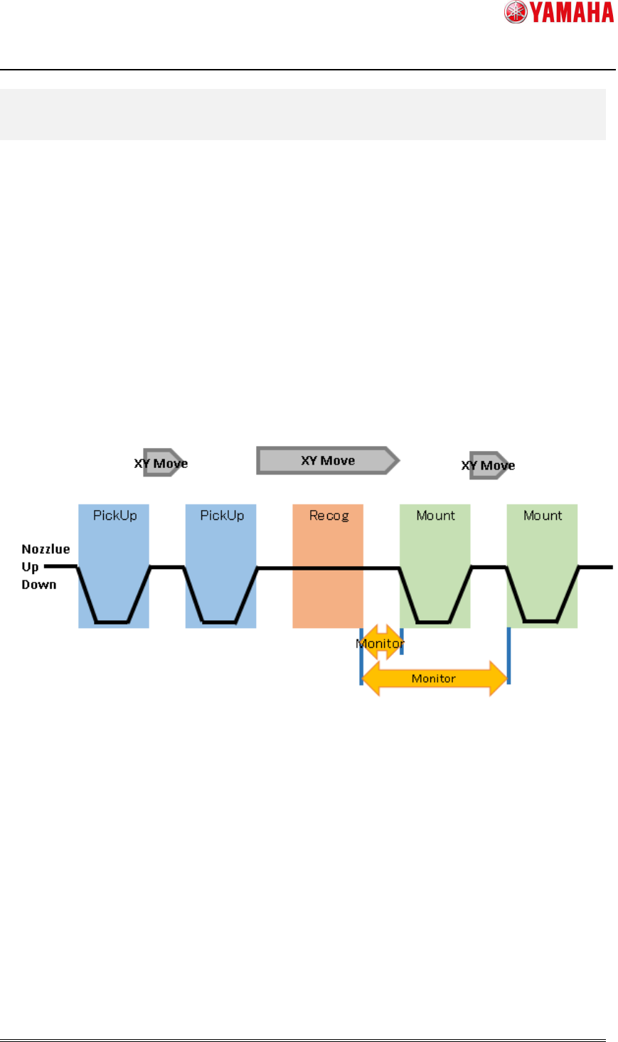
Between “after camera recognition of picked parts” and “before mounting”, vacuum level is
monitored for checking of parts existence. It memorizes the highest vacuum level, and
judges “parts fall” if the vacuum level drops below a certain level(※) from the peak.
(※) Specified for each nozzle type in Machine Setting.
3.2 Period of Chip Vacuum Check
Vacuum level is monitored between “after camera recognition of picked parts” and “before
mounting” for all heads(nozzle type) that are set with [Chip Vacuum Check] active and also
picking parts.
Fig3.1
Vacuum level monitoring time
2nd SMT Engineering Division Software Group
IM Operations
YAMAHA MOTOR CO., LTD
MDOC-SOFT50395
5/11
3.3 Timing to output errors
Between “after camera recognition of picked parts” and “before mounting”, it monitors
vacuum level for checking of parts existence. The error is not output just after a chip is
dropped off. Timing to display the error is as follows.
When chip is dropped from mounting head
The error message is displayed when XY-axis arrives at the mounting position. At this
time, the error message is displayed for each error head.
When chip is dripped from other than mounting head
The error occurs when mounting of mount head is completed. At this time, the error
message is displayed for each error head.
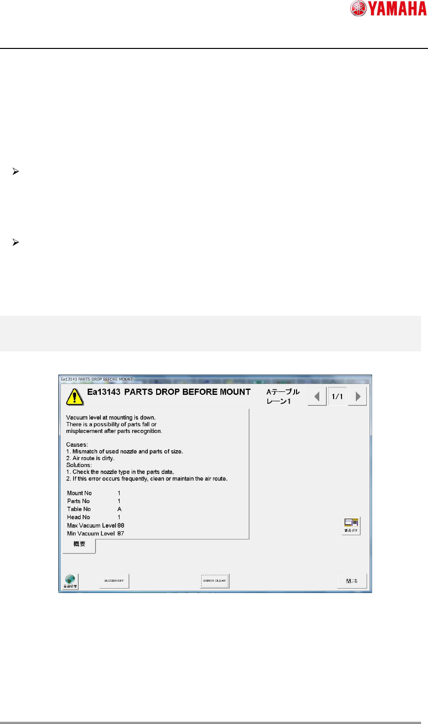
4. Error Message
When parts fall is detected, the following error message is displayed.
Fig 4.1 Error message dialog
When parts fall is detected, the error message is displayed for each head.
By clicking the [Parts Adj] button on the message, you can see the picking condition and
vacuum level of the error head.
2nd SMT Engineering Division Software Group
IM Operations
YAMAHA MOTOR CO., LTD
MDOC-SOFT50395
6/11
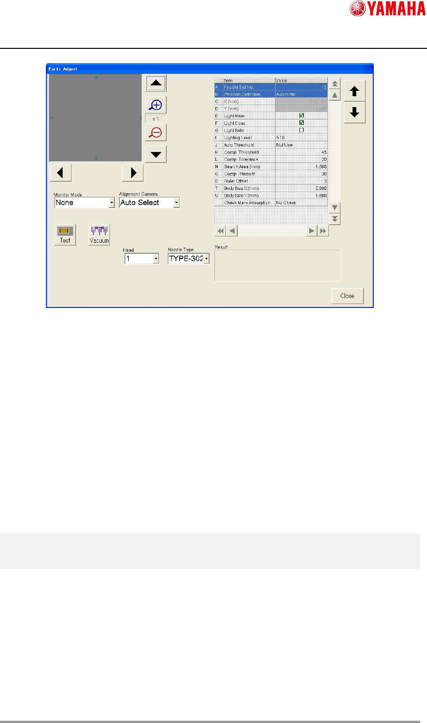
Fig 4.2 Parts Adjust screen
When parts adjustment is executed on the [Parts Adjust] screen opened from the Ea13143
message, it is not allowed to edit the parts data on the right. Also, parts data is not updated
by Test. (
※
)
Parts Adjust screen opened from the Ea13143 message is used only for confirmation.
(※) When “Test” is executed on the [Parts] - [Parts Adj] screen, [Comp. Intensity] in parts data is
automatically updated. Meanwhile, when it is executed on the [Parts Adj] screen opened from the Ea13143
message, [Comp. Intensity] is not updated.
5. Recovery from error
When “Ea13143: PARTS DROP BEFORE MOUNT” occurs, press the [Parts Adj] button on
the message, and execute “Test” to check the picking condition of the error nozzle. If no chip
is on the nozzle, it may have been dropped on a board. In that case, please remove it. Then
close the error message and press the [START] button. All error heads perform dumping
action and auto-running starts.