3OM-1011-001.pdf - 第252页
(Cause 1) The pick-up position has shifted from the specified one in the X direction. (Cause 2) The tapered part of the vacuum nozzle end or the diffusion plate is stained. (Cause 3) Improper parameters are set in the &q…
(Cause 1) The pick-up position has shifted from the specified one in the X direction.
(Cause 2) The tapered part of the vacuum nozzle end or the diffusion plate is stained.
(Cause 3) The lighting is dark.
(Cause 4) An improper parameter is set in the "DIRECTION" data box of the label "LEAD
DATA".
(Reset Procedure in the case of Causes 1, 2, 3 and 4)
Reset Procedure
(1) Check the component and the tape feeder.
(2) Clean the vacuum nozzle end or the diffusion plate.
5. Component Recognition Error Code and List of Error Messages
0305-001 4-46 Tg0859-PM-ER
Error Code Display A Display B
2034Y020 CORNER DETECTION
to 029 ERROR
Note:Y represents “1”, “2”, or
“4”.
NOZZLE PROTRUSION OCCUPIES MORE THAN 2
CORNERS.
2034Y030 CORNER DETECTION
to 039 ERROR
Note:Y represents “1”, “2”, or
“4”.
RECOGNITION ABORTED BECAUSE OF IMPROPER
COMPONENT HANDLING.
(Cause 1) This is the device’s self-diagnostic message.
(Reset Procedure in the case of Cause 1)
Reset Procedure
(1) Press the [ZERO] button to return all the axes to their original positions.
(2) Re-start.
(3) If the device can’t be re-started, contact our service personnel.
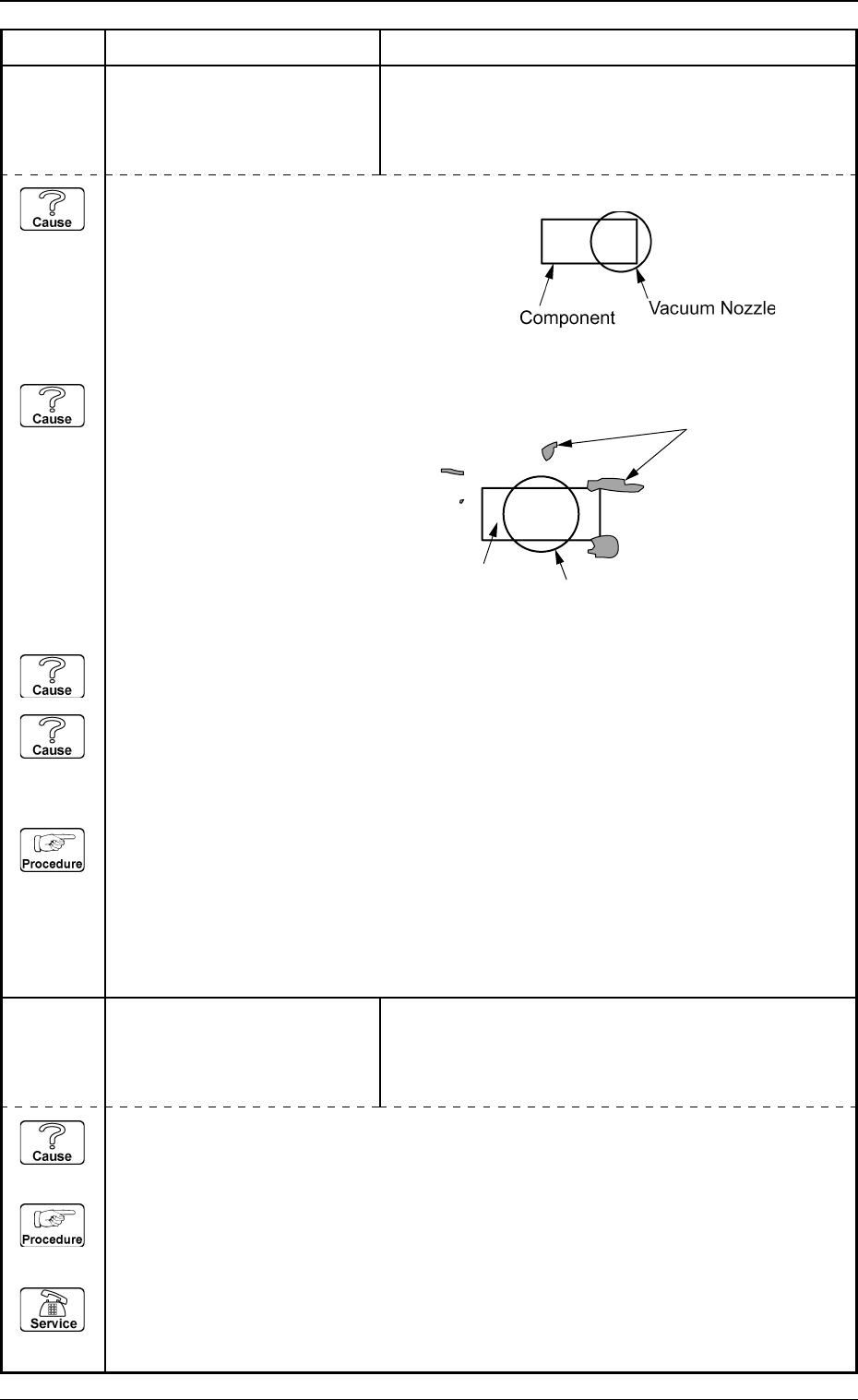
Fig. 3D5
Fig. 3D6
Dirty Spots
Component
Vacuum Nozzle
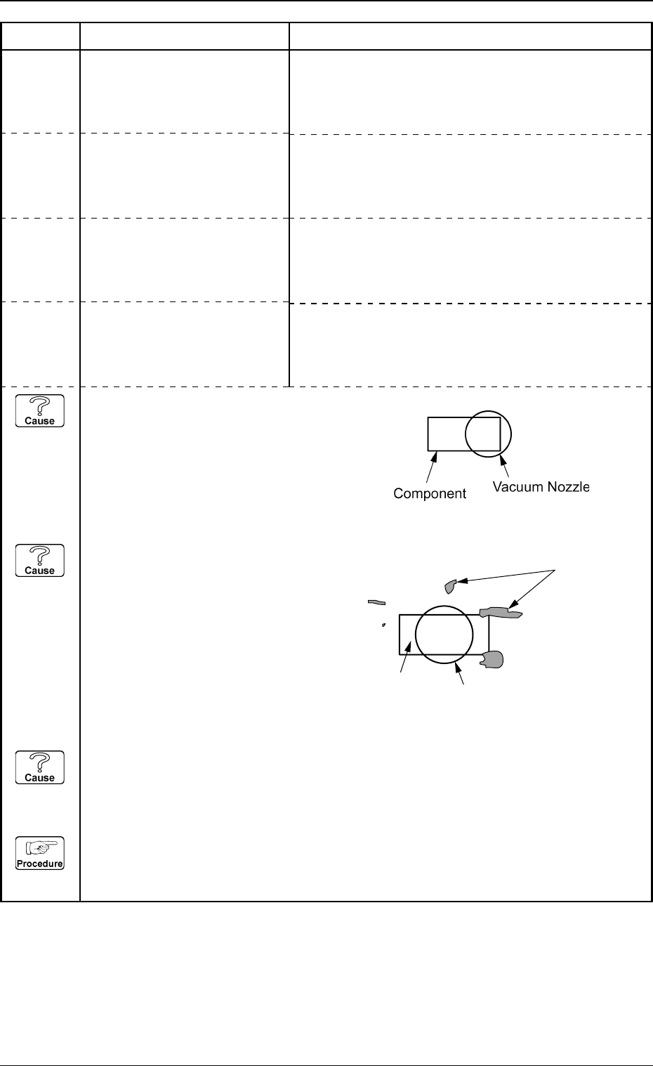
(Cause 1) The pick-up position has shifted from the specified one in the X direction.
(Cause 2) The tapered part of the vacuum nozzle end or the diffusion plate is stained.
(Cause 3) Improper parameters are set in the "FORM", "X SIZE", and "Y SIZE" data boxes of the
label "CORNER DATA".
(Reset Procedure in the case of Causes 1, 2 and 3)
Reset Procedure
(1) Check the component and the tape feeder.
(2) Clean the vacuum nozzle end or the diffusion plate.
5. Component Recognition Error Code and List of Error Messages
0305-001 4-47 Tg0859-PM-ER
Error Code Display A Display B
2034Y500 CORNER DETECTION
to 509 ERROR
Note:Y represents “1”, “2”, or
“4”.
CORNER (UPPER-LEFT) NOT FOUND.
2034Y700 CORNER DETECTION
to 709 ERROR
Note:Y represents “1”, “2”, or
“4”.
CORNER (LOWER-RIGHT) NOT FOUND.
2034Y800 CORNER DETECTION
to 809 ERROR
Note:Y represents “1”, “2”, or
“4”.
CORNER (UPPER-RIGHT) NOT FOUND.
2034Y600 CORNER DETECTION
to 609 ERROR
Note:Y represents “1”, “2”, or
“4”.
CORNER (LOWER-LEFT) NOT FOUND.
Fig. 3D7
Fig. 3D8
Dirty Spots
Component
Vacuum Nozzle
(Cause 1) The recognition processing time of the selected component is different.
(Reset Procedure in the case of Cause 1)
Reset Procedure
(1) Check the selected component and the parameter set in the “RECOG. TIME” text box of the
label “SPEED DATA” in the component library data.
(2) If a wrong parameter is set in the component library data, correct it.
5. Component Recognition Error Code and List of Error Messages
0305-001 4-48 Tg0859-PM-ER
Error Code Display A Display B
2036910M EXTERNAL SHAPE DETEC-
TION ERROR
Note:M represents “1” through
“6”.
LINEAR EDGE M NOT FOUND.
20369100 EXTERNAL SHAPE DETEC-
TION ERROR
SOME LINEAR EDGES CANNOT BE DETECTED.
2037X001 RECOGNITION OVERTIME
ERROR
Note:X represents “1” through
“4”.
RECOGNITOIN TOOK TOO MUCH TIME.
(Cause 1) When the selected component is picked up, the pick-up position and angle have shifted
greatly from the specified ones.
(Reset Procedure in the case of Cause 1)
Reset Procedure
(1) Check the selected component and the tape feeder.