3OM-1011-001.pdf - 第35页
2. Cause and Remedy of T ape Feeder Installation Error (Lifted Feeder) Whenever a feeder installation error (lifted feeder) is detected, the machine stops instantaneously in an error condition and an error message is iss…
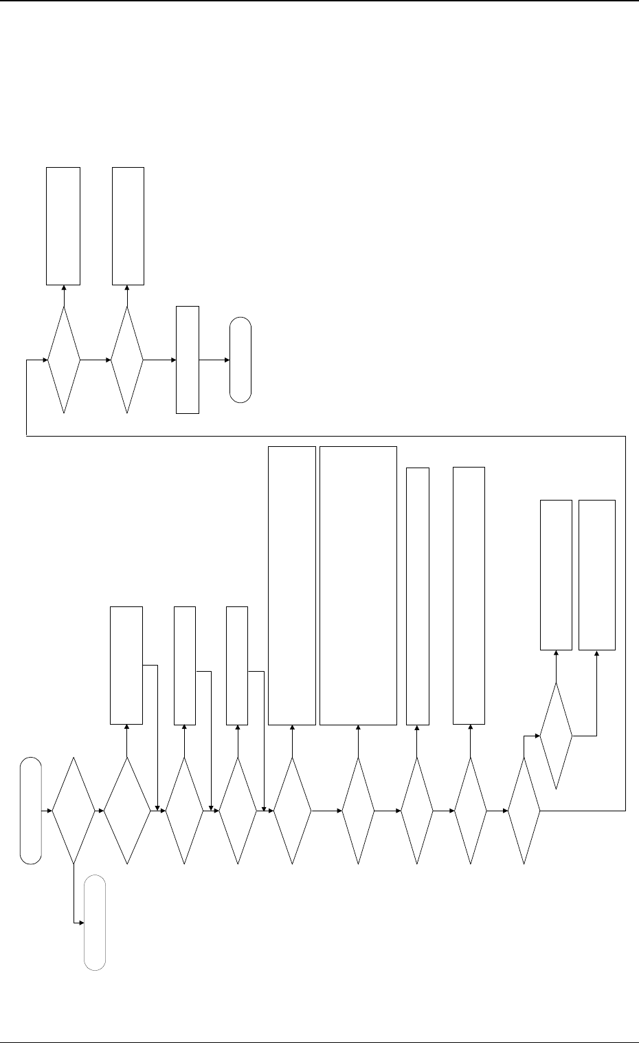
1.3.4 Servo Power Supply
Symptom
Beam A or B is not powered.
The servo power lamp on the rear or the front side does not illuminate.
No sound (operating sound) is produced from the electromagnetic contactor.
............ etc.
0305-001 1-21 Tg0859-PM-ER
1.3 Power Supply
Fig. 3A27
Check the power supply for the X/
Y axis of Beams A and B.
Is the power for loads
supplied?
Is the LED of the [POWER
ON] button "ON" in green?
Are the [READY] button on
the rear side pressed and
the material supply door
locked?
Set the [OPERATION/SET UP]
switches on both front and rear sides
back to the "OPERATION" side.
Check whether neither Q311A, 301A, 302A, 303A, 304A nor Q311B, 301B, 302B, 303B,
304B is tripped.
If tripped, confirm that no abnormality is found on the loaded side and then turn on the
power breaker crank again.
Check whether the relays (K101A/101B) are working.
Are the safety relays
(K131A/K131B) working?
Check whether the fuses (K051A/K051B) have melted, breaking the circuits.
Confirm that the electromagnetic contactors (KM111A, 1113A, 1114A, 101A, 102A/
KM111B, 1113B, 1114B, 101B, 102B) are "OFF".
Confirm that no contacts have been welded.
Confirm that Relay K65 is "OFF".
Confirm that Relays K61, K62, K123A, and 124A/K123B, and 124B are "ON".
Confirm that Relays K115A/K115B are "ON".
Confirm that Relay K122A is "ON". (Confirm that the Y-axis mechanical stopper has
returned.)
Check whether each load is
normal.
Is an alarm produced from
the servo driver?
Check the contents of the alarm.
Check the servomotor driver and motor wiring.
Check how the relays (K102A, 103A/K102B,
103B) are working.
Check the wiring.
Check the SDS output node.
END
To "1.3.3 Power Supply for
Main Loads"
Is the [OPERATION/SET
UP] switch set to the
"OPERATION" side?
(Both Front and Rear Sides)
Press the [READY] button to lock the
material supply door.
Are the supply and
maintenance cover closed?
Close the supply and maintenance
cover.
Is the circuit breaker
tripped?
Is the electromagnetic
contactor "ON"?
Check how the electromagnetic contactors (KM111A, 1113A, 114A/KM111B,
1113B, 1114B) are working.
Check the wiring.
Are the relays (K102A,
103A/K102B, 103B) "ON"?
Check the sensor.
Check the interlock board.
Check the wiring.
Are the relays (K111A/
K111B) "ON"?
Is the electromagnetic
contactor "ON"?
Check how the electromagnetic
contactors (KM101A, 102A/KM101B,
102B) are working.
Check the wiring.
Are the servo power lamps
(HD51A/HD51B) "ON"?
Check the lamps.
Check the wiring.
YES
YES
NO
NO
NO
NO
YES
YES
NO
YES
NO
YES
YES
NO
NO
YES
NO
NO
YES
YES
NO
YES
NO
YES
YES
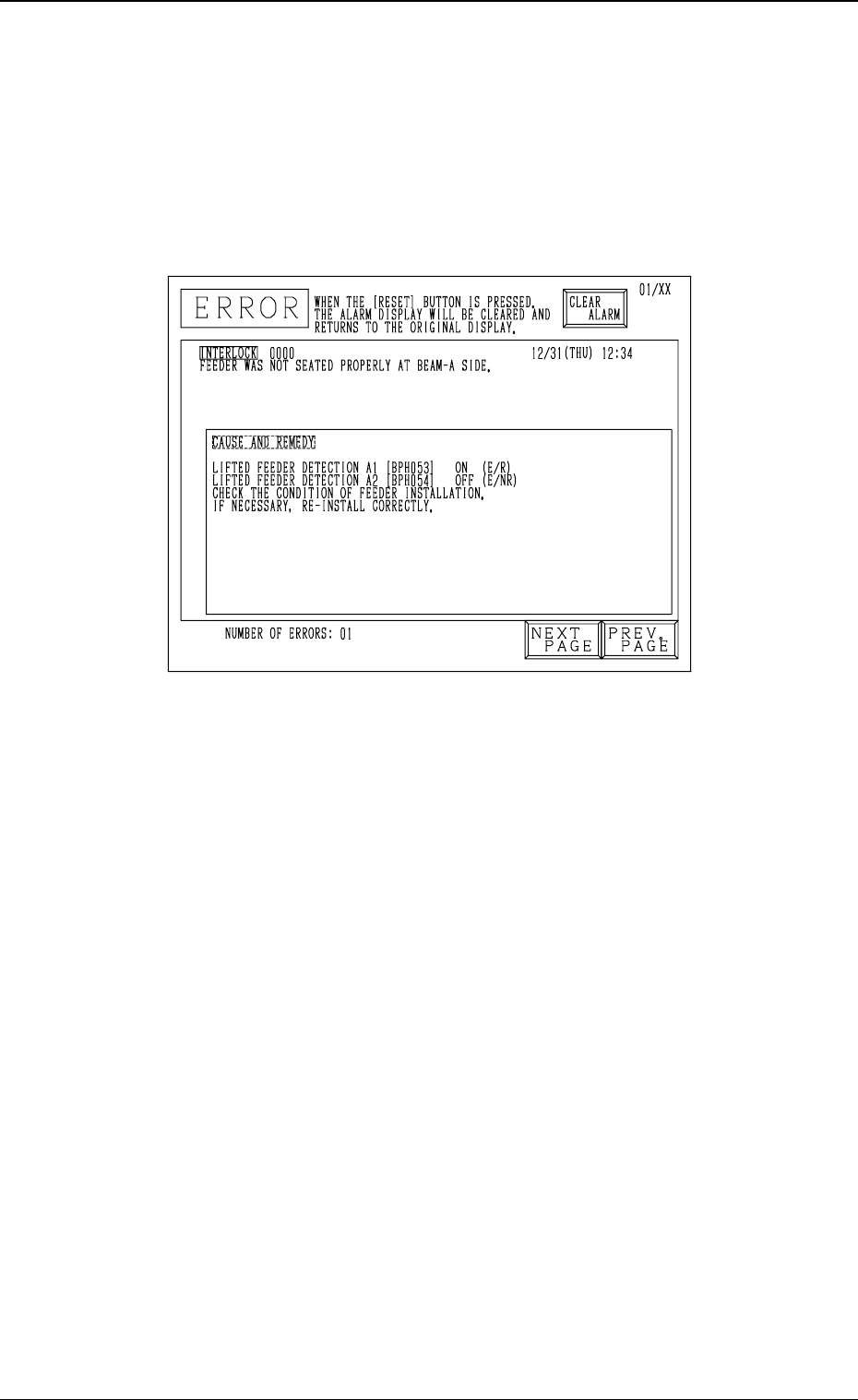
2. Cause and Remedy of Tape Feeder Installation
Error (Lifted Feeder)
Whenever a feeder installation error (lifted feeder) is detected, the machine
stops instantaneously in an error condition and an error message is issued re-
gardless of machine operation mode (“RUN”, “PAUSE”, or “STOP”) except
for the time when a feeder is replaced with the supply cover being opened
because machine protection has top priority.
Cause of Feeder Installation Error (Lifted Feeder)
• The tape feeder is not seated correctly.
• The suppressor of the tape feeder is disengaged and kept afloat (lifted).
• A component has popped out from the tape feeder or the vibratory stick
feeder and is shielding the lifted feeder detection sensor.
• A vertical component is picked up because the pick-up position has deviated
from the correct one or the tape is not fed normally and the picked compo-
nent is shielding the sensor at the position where the head has ascended.
• The foreign substance was detected.
• The amount of slack of the tape is large.
Remedy
(1) Press the [RESET] button to cancel the error condition.
(2) Press the [READY] button on the side where the lifted feeder was de-
tected to unlock the supply cover.
(3) Open the supply cover and remove the cause of the lifted feeder detec-
tion.
(4) Confirm that the light is emitted and received by the lifted feeder detec-
tion sensor.
(Confirm that the indicator lamp of the sensor is “ON”.)
(5) Close the supply cover and press the [READY] button to lock the cover.
(6) Press the [ZERO] button to zero each device.
(7) After all devices are zeroed completely, press the [START] button to re-
start the operation.
0305-001 1-22 Tg0859-PM-ER
2. Cause and Remedy of Tape Feeder Installation Error (Lifted Feeder)
Fig. 3A28
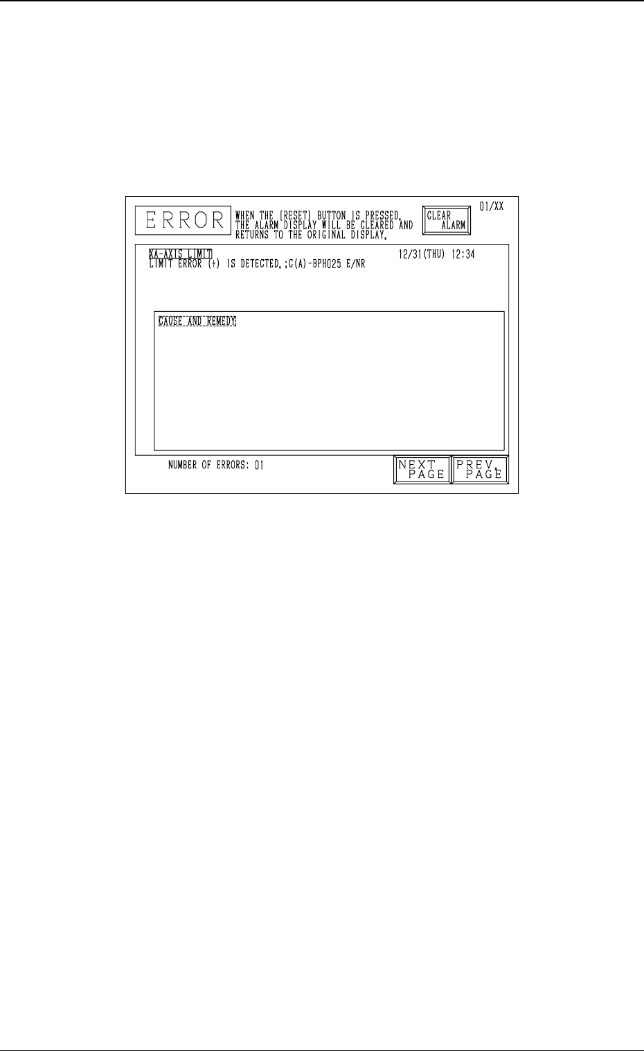
3. Cause and Remedy of Nozzle Excessive Pushing
Error
Whenever a nozzle excessive pushing error is detected, the machine stops in-
stantaneously in an error condition and an error message is issued regardless
of machine operation mode (“RUN”, “PAUSE”, or “STOP”) because machine
protection has top priority.
Cause of Nozzle Excessive Pushing Error
• A value different from the actual height is entered as “HEIGHT” data in the
component library data.
• A value different from the actual nozzle length is entered as “LENGTH”
data in the nozzle data.
• The offset data is illegal.
• The machine tried to place a component on a previously-placed one due to
an error, etc., in the pattern program.
Remedy
(1) Press the [RESET] button to cancel the error condition.
(2) Zero the up/down shaft.
(3) Remove the cause of the error.
(4) Zero each shaft.
(5) Re-start the operation.
0305-001 1-23 Tg0859-PM-ER
3. Cause and Remedy of Nozzle Excessive Pushing Error
Fig. 3A29