00198156-01_AI_Long-Board-Option_EN.pdf - 第16页
Installing Installing the LBO E Kit 2.1.2 Installation 16 Assembly Instructions E by SIPLACE 2.1.2.3 2 . 1 . 2 . 3 S t o p p e r ( A ll V e r s io n s ) Stopper (All Versions) Right side Left side ► Undo the cou ntersunk…
Installing
2.1.2 Installation Installing the LBO E Kit
Assembly Instructions E by SIPLACE 15
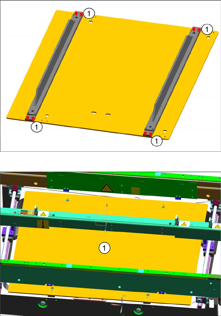
► Remove the stiffening fillet screws (1).
► Fit the stiffening fillet to the "E-series lifting table plate LBO" [03108017
-
xx] (1).
► Refit the lifting table assembly to the conveyor frame using the same M6x30 securing screws.
Installing
Installing the LBO E Kit 2.1.2 Installation
16 Assembly Instructions E by SIPLACE
2.1.2.3
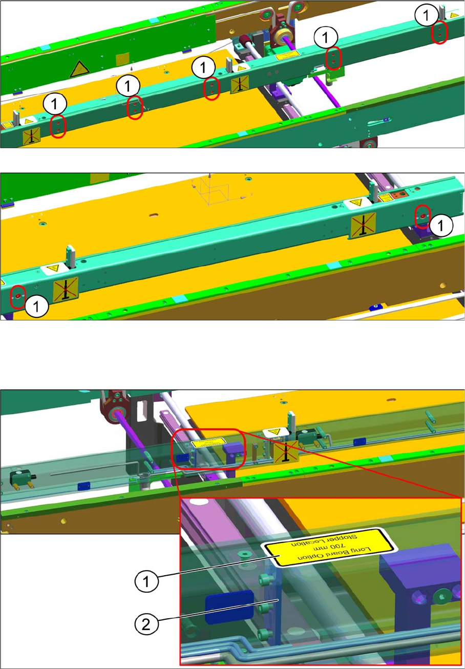
2.1.2.3 Stopper (All Versions)
Stopper (All Versions)
Right side
Left side
► Undo the countersunk M3x6 screws and M4x8 screws (1) to access the internal parts of the stopper
rail.
► Remove the 700 mm LBO sticker (1) from the cover
► Remove the cover (2).
Installing
2.1.2 Installation Installing the LBO E Kit
Assembly Instructions E by SIPLACE 17
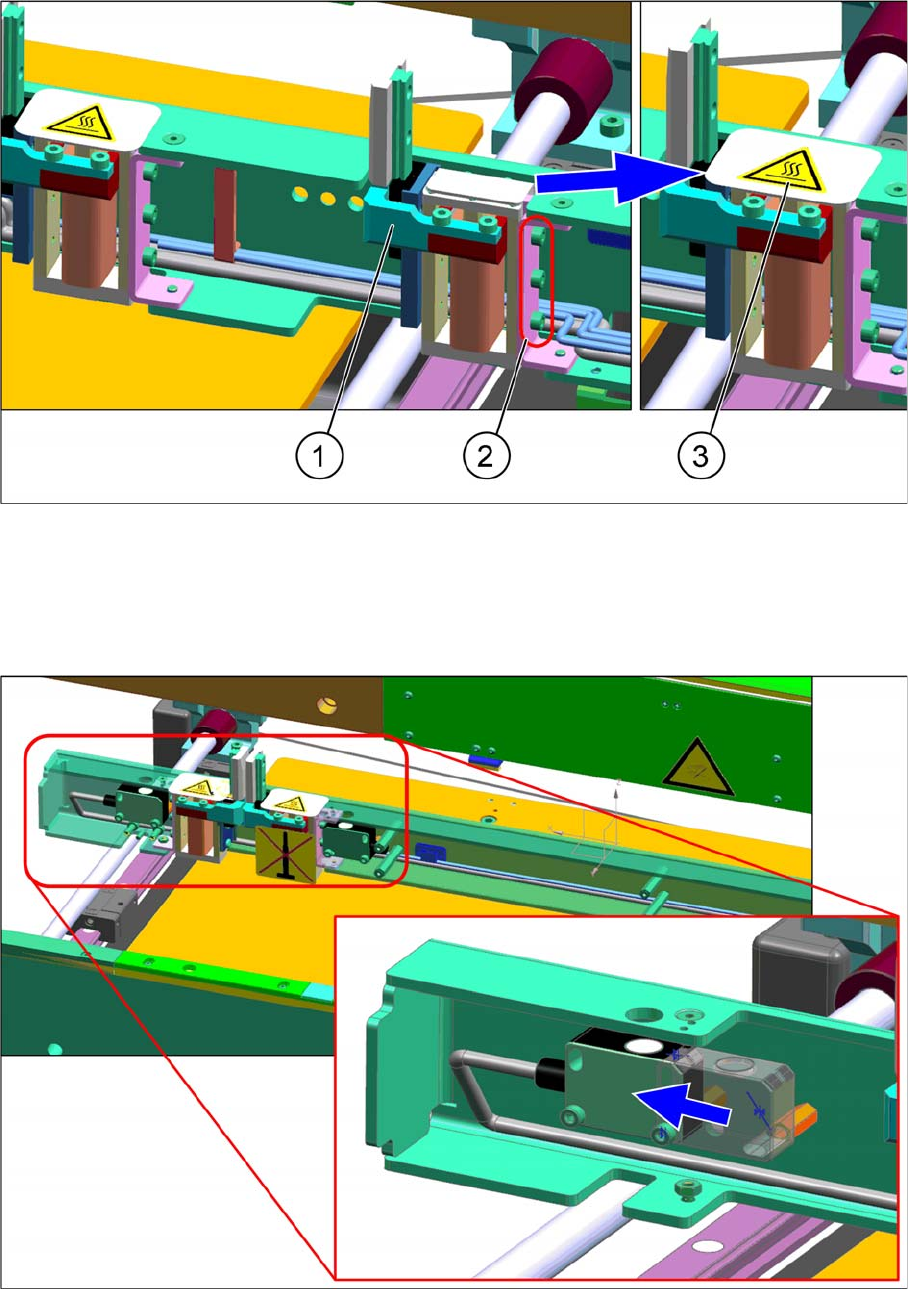
► Install the "E-series conveyor stopper unit" [03106565-xx] (1) with " M3x6 cap screws" (2)
► Connect the cable.
► Paste the "Hot temp warning label" [03107383-xx] (3) over the gap around the external area of the
stopper.
► Shift the sensor toward the output area.