00198156-01_AI_Long-Board-Option_EN.pdf - 第20页
Installing Installing the LBO E Kit 2.1.2 Installation 20 Assembly Instructions E by SIPLACE ► Assemble the individual extension panel modules . ► Assemble the extension panels to the side panels using the M6x1 2 button …
Installing
2.1.2 Installation Installing the LBO E Kit
Assembly Instructions E by SIPLACE 19
2.1.2.4
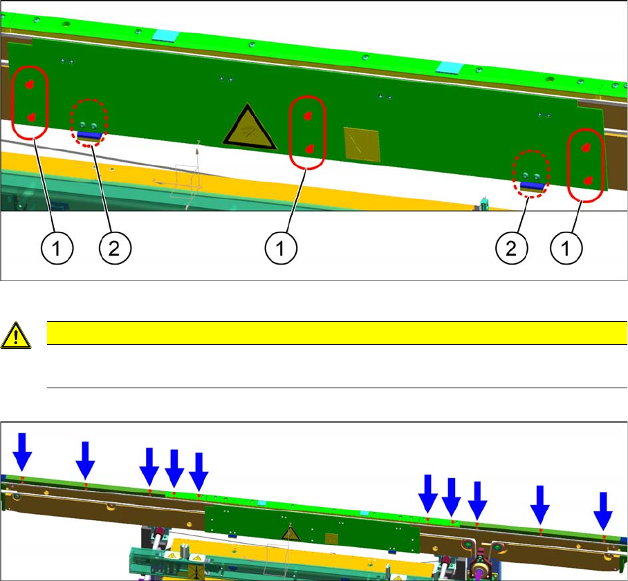
2.1.2.4 Clamping Plate and Belt (Only 1200 mm Version)
Clamping Plate and Belt (Only 1200 mm Version)
► Remove the screws (1) to release the clamping plate.
► Remove all screws on the top panels.
► Remove the belt and replace it with the "BRECOFLEX Belt 10T5/4000" [03109841-xx].
CAUTION
Springs
When removing the clamping plate, watch out for the springs (2).
Installing
Installing the LBO E Kit 2.1.2 Installation
20 Assembly Instructions E by SIPLACE
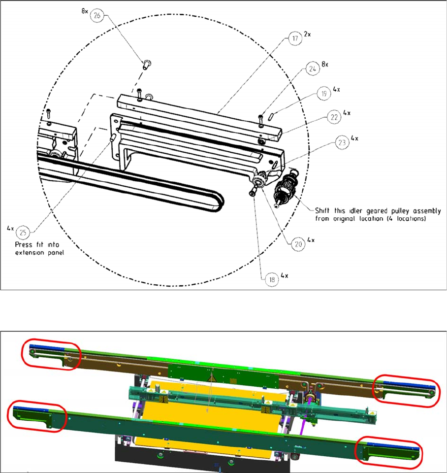
► Assemble the individual extension panel modules.
► Assemble the extension panels to the side panels using the M6x12 button head screw
[03040122
-
xx].
► Assemble the belt and the clamping plate along with the top panels. The clamping plate is needed
to guide the spring back to the original position.
► Do this for both side panels.
Installing
2.1.2 Installation Installing the LBO E Kit
Assembly Instructions E by SIPLACE 21
2.1.2.5
2.1.2.5 Cable Harness (All Versions)
Cable Harness (All Versions)
► Connect the designated cable harness as per below conveyor option configurations.
Connections points are in the Standard flow and Reverse flow schematics.
LBO E 1200 [03110518-xx] and LBO E 1030 [03108019-xx]
▪ Standard flow (Right Fix)
– Cable, stopper, LBO, trk1 [03101844-xx]
– Cable, PCB sensor, LBO, trk1 [03101834-xx]
– Cable, stopper, reverse, trk1 reverse [03108854-xx]
– Cable, stopper ext, LBO Reverse trk 1 [03114850-xx]
▪ Reverse flow (Left Fix)
– Cable, stopper, LBO, trk1 [03101844-xx]
– Cable, stopper ext, LBO, trk 1 [03114849-xx]
– Cable, PCB sensor, LBO, trk1 [03101834-xx]
– Cable, stopper, reverse, trk1 reverse [03108854-xx]