00197396-02_AI_Serviceflap_X-Series_S_DE_EN.pdf - 第45页
3 Installation 3.4 Fitting Hinges and Sliders Assembly Instructions / Montageanleitung SIPLACE X-Series S Service Flap Serviceklappe 07/2019 45 3.4 Fitting Hinges and Sliders NOTICE Pay attention to the hinge version Mak…
3 Installation
3.3 Converting the Side Cover
44 Assembly Instructions / Montageanleitung SIPLACE X-Series S Service Flap Serviceklappe 07/2019
3.3 Converting the Side Cover
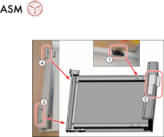
Fig.9: Converting the side cover
► Place the side cover down on a suit-
able work surface.
► Fasten the actuating bracket for the
safety switch using two screws(1).
► Fasten the handle with two screws(2).
Handle assy SIPLACE X-Series S
for locations 1 / 3 [03112951‑xx]
for locations 2 / 4 [03112952‑xx]
► Remove the reinforcements at (3)
and (4).
3 Installation
3.4 Fitting Hinges and Sliders
Assembly Instructions / Montageanleitung SIPLACE X-Series S Service Flap Serviceklappe 07/2019 45
3.4 Fitting Hinges and Sliders
NOTICE
Pay attention to the hinge version
Make sure that you use the correct hinges, as the retrofit kit includes both versions (left and
right): right for location 4 and 2, left for location 1 and 3.
Your hinges might vary somewhat. However, the assembly procedure is the same.
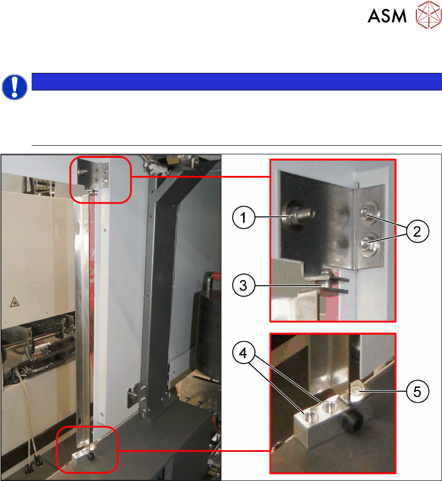
Fig.10: Fitting hinges and sliders
► Fasten the hinge at the top at the points marked (1) and (2) the EMC tape at the point marked (1).
Make sure that you use the correct variant for locations 1/3 and 2/4. Do not yet tighten the screws.
► Fasten the lower part of the hinge with two screws (4).
► Fasten the slider accordingly to "hinge top" (3) and "hinge lower part assy"(5).
3 Installation
3.5 Fitting the Security Switch
46 Assembly Instructions / Montageanleitung SIPLACE X-Series S Service Flap Serviceklappe 07/2019
3.5 Fitting the Security Switch
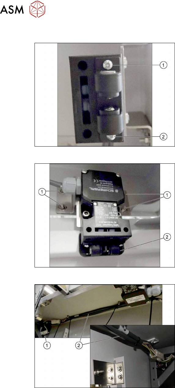
Fig.11: Fasten the ball holder
The safety switch is prefitted to the support
plate. The ball holder still needs to be fitted,
preferably before you install the safety
switch in the machine.
► Fasten the ball holder down on the
safety switch at the points marked (1)
and (2).
Fig.12: Support plate with safety switch fastened to it
► Use four nuts and washers to fasten
the support plate with the safety switch
to the inside of the cover (1)
. The point marked (2) shows the ball
holder when fitted.
Fig.13: Cables
► Unplug the line from the existing safety
switch at the press-fit connection under
the center cover and integrate the
safety switch into the safety loop (1).
► Run the cable for the new safety switch
parallel to the existing one(2).