00196678-0102_RI_CAN-Knoten_X-Serie70x_De+EN.pdf - 第40页
Introduction Abbreviations Safety Instructions for the Gantry 40 Retrofit Instructions CAN Node X Series SW70x 4.3 Abbreviations PA Placement area CO Component COT Changeover table COT-i Changeover table – insert (compo …
Introduction
Safety Instructions for the Gantry Preparatory Work...
Retrofit Instructions CAN Node X Series SW70x
39
X Alternative: Attaching warning signs
If a machine can be locked, it must be. However, there are situations where energy isolating devices
cannot accommodate locks. In these cases, the energy isolating devices must be tagged to warn
employees that the machine is de-energized for servicing. The tag or label must be securely
fastened, it must be placed in a position visible to all and it may only be removed by the person who
attached it.
X Release of stored energy
Stored energy in the compressed air supply or electrical energy in electrolytic capacitors must be
released by appropriate means.
After switching off the placement machine wait until the voltages and the compressed air have
discharged, to be able work without any risk.
X Testing the lock out.
Testing the lock out can be done simply by pressing the start button.
X The following steps must be taken to restore the machine to operation.
X Check the area. Authorized employees should remove all of their tools and reinstall all guards.
X Notify all affected employees.
X Before removing even one lock or tag, inform all workers in the area that the machine is going to be
restarted.
X Remove locks/tags
X Every authorized employee has to remove his own lock and shut it away.
X Turn the machine on. Authorized workers should observe the equipment in operation to insure
repairs were done correctly.
Testing
Service personnel may test the circuits by energizing the circuit for a short period of time without voiding
the lock out procedure provided. This may be done only when no other work is being performed by any
other person on the equipment being tested.
It is extremely important that all remote start switches be tagged with the "Do Not Operate" tag to prevent
inadvertent operation of the equipment during these periods.
Responsibilities
It shall be the responsibility of the maintenance and service personnel to make sure this procedure
is adhered to.
It shall be the responsibility of the maintenance and service personnel's immediate supervisor to
instruct his personnel on this procedure.
It shall be the responsibility of the Safety Officer with assistance from the Safety Committee, Health
Service Department, and the various managers and vice-presidents to administer the Lock Out / Tag
Out Procedure.

Introduction
Abbreviations Safety Instructions for the Gantry
40 Retrofit Instructions CAN Node X Series SW70x
4.3 Abbreviations
PA Placement area
CO Component
COT Changeover table
COT-i Changeover table – insert (component trolley feed device)
C&P Collect&Place
C&P12 Collect&Place head with 12 segments
C&P20 Collect&Place head with 20 segments
C&P6 Collect&Place head with 6 segments
CPP Collect&Pick&Place head
ESD Electrostatic sensitive device
EMC Electromagnetic compatibility
PCB Printed circuit board
P&P Pick&Place
SC Station computer
TH TwinHead
VS Vision system
WPC Waffle pack changer
WPC4 Waffle pack changer version 4
WPC 5 Waffle pack changer version 5
Overview
General Description of CAN Node
Retrofit Instructions CAN Node X Series SW70x
41
5Overview
5.1 General Description of CAN Node
These retrofit instructions are intended for the upgrade of the X series with the number B600-B751 to
CPP capability. From serial number B752 the CAN node is already installed in series.
A machine upgrade to CPP capability with a number lower than B600 must be considered as a project.
In this case please contact your SIPLACE Service team in Munich.
The introduction of the "CAN node NC tape cutter X/HF" [03052927-xx] (new tape cutter control board )
includes the replacement of the 1-wire hub with the CAN bus control of the X series nozzle changer.
Additionally, this CAN node also controls the query of the component reject bin and the nozzle station.
It is not possible to mix locations with the 1 wire hub and CAN nodes.
This new control board can be used also with older types of tape cutters. In this case, the CAN node
must be adjusted in order to react as an older tape cutter control board.
Attention: From SW70x the NC can be addressed only via the CAN nodes. The 1 wire bus is then only
used for the temperature sensors.
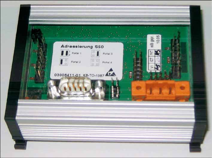
5-1: Control board for tape cutter, old [03006411-xx]