00196678-0102_RI_CAN-Knoten_X-Serie70x_De+EN.pdf - 第45页
Installation Preparatory Steps Retrofit Instructions CAN Node X Series SW70x 45 6 Inst allation 6.1 Prep aratory Step s X See also section (4.2 Preparatory Wo rk... J 38) . X Move all component trolleys out of th e mac…
Overview
Control Unit on Tape Cutter (CAN Node Module) Description of CAN Node LEDs
44 Retrofit Instructions CAN Node X Series SW70x
Description of CAN node NC tape cutter module
This board is backwards compatible to the old tape cutter board. It can be used at X, HF and D series
machines.
The CAN processor decides which functions need to be checked at the individual locations, depending
on the cables connected and the type of DIP switched set.
1)
Not all gantries may be available, depending on the machine type.
2)
Even if there is no nozzle changer installed and only the tape cutter needs to be controlled, this switch
still needs to be set to OFF for the reject bin query and the reject station.
X series machine with CAN node
The cable of the machine (cable harness machine) has to be by-passed as shown in the list:
*112: Gantry 1: 10/11/12 by-passed
*122: Gantry 2: 11/12 by-passed
*132: Gantry 3: 10/12 by-passed
*142: Gantry 4: not by-passed
5.4.1 Description of CAN Node LEDs
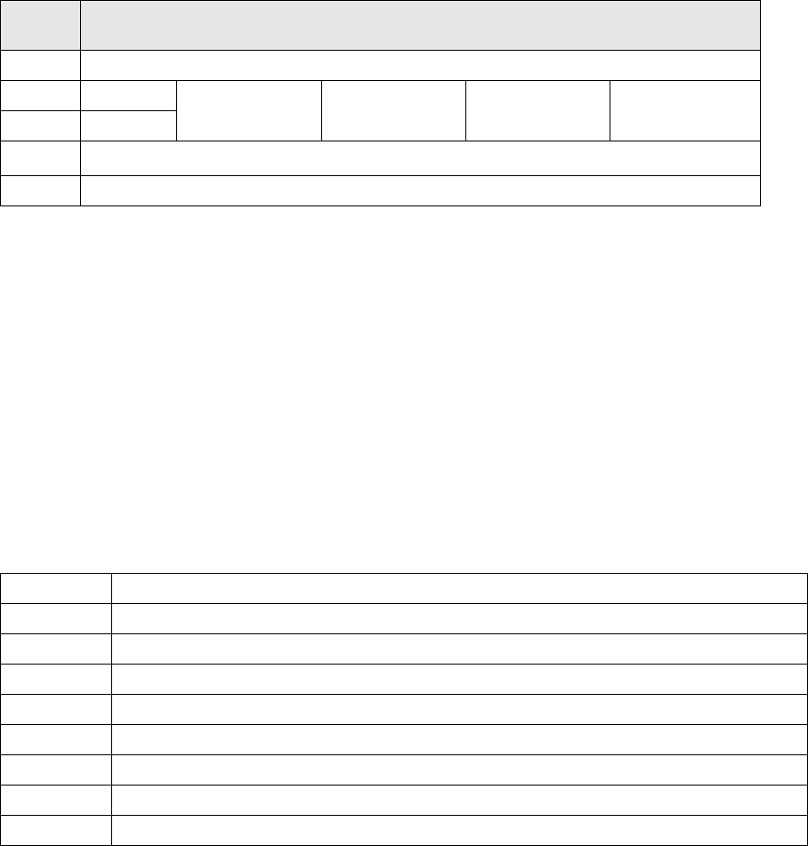
DIP
switch
DIP switch meaning
1ON: Setting the CAN ID via DIP switch 2 and 3 – OFF: Cable Select
2 CAN - ID 0
ON: Gantry 1
1)
ON
OFF: Gantry 2
1)
ON
ON: Gantry 3
1)
OFF
OFF: Gantry 4
1)
OFF: Cable select
3 CAN - ID 1
4
ON: Only tape cutter – OFF: Nozzle changer and tape cutter
2)
5ON: Module in reset-mode – OFF: Module in standard mode
DIP switch group S3 - overview
LED Function
V39 Component reject bin
V45 Nozzle reject bin
V41 CPU green status LED
V43 CPU red status LED
V44 NC1 light barrier 24V
V42 NC1 valve active
V40 NC2 light barrier 24V
V38 NC2 valve active
Installation
Preparatory Steps
Retrofit Instructions CAN Node X Series SW70x
45
6 Installation
6.1 Preparatory Steps
X See also section (4.2 Preparatory Work...
J
38) .
X Move all component trolleys out of the machine with the help of the software.
X Perform shut down and switch off the machine.
X Always secure the machine against unauthorized reactivation.
X Disconnect the machine from the power and pneumatic supplies.
NOTE:
The SW70x does not support S feeders. Any component trolley feed units need to be replaced
with X feed-in devices.
Read the corresponding instructions:
MTC 2 and component trolley feed-in device SIPLACE HF series / X series, issue 07/2009, d +
e [00193892-04]
Chapter 4.9.4 Replacing the component trolley feed-in assembly for X series machines
[03015680-xx]
NOTE:
In a 1 gantry placement area the component trolley feed-in device needs to be loosened at
location 2 or 4 and pulled slightly out, so that the cable can be run. Read the corresponding
instructions:
Service manual and setting instructions for X series machines - 04/2009 - DE [00194439-08]
Chapter 4.9.4 Replacing the component trolley feed-in assembly for X series machines
[03015680-xx] or the instructions:
MTC 2 and component trolley feed-in device SIPLACE HF series / X series, issue 07/2009, d +
e [00193892-04]
Installation
Replacing the Tape Cutter Control Board with the CAN Nodes
46 Retrofit Instructions CAN Node X Series SW70x
6.2 Replacing the Tape Cutter Control Board with the CAN Nodes
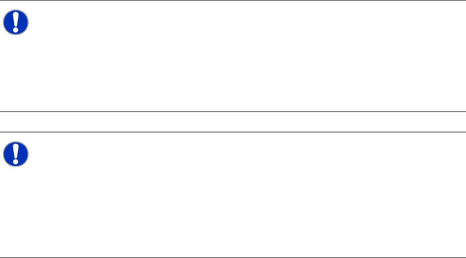
6-1: Dismantling the tape cutter control board, old
X Loosen the old tape cutter control board with
the mounting rail from the tape cutter (2
screws). You can now remove the cover on the
old control board.
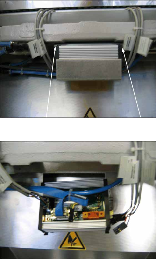
6-2: Disconnecting the cable from the tape cutter control board
X Disconnect all cables from the old tape cutter
controller.