GWS 6-100 S角磨机说明书.pdf - 第9页
English | 9 Bosch Power Tools 1 609 92A 2V9 | (23.11.16) Product Description and Specifica- tions Read all safety warnin gs and all instruc- tions. Failure to follow the warnings and in- structions may result in electric…
8 | English
1 609 92A 2V9 | (23.11.16) Bosch Power Tools
Do not attach a saw chain woodcarving blade or
toothed saw blade. Such blades create frequent kickback
and loss of control.
Safety warnings specific for Grinding and Abrasive
Cutting-Off operations
Use only wheel types that are recommended for your
power tool and the specific guard designed for the se-
lected wheel. Wheels for which the power tool was not de-
signed cannot be adequately guarded and are unsafe.
The grinding surface of the centre depressed wheels
must be mounted below the plane of the guard lip. An
improperly mounted wheel that projects through the plane
of the guard lip cannot be adequately protected.
The guard must be securely attached to the power tool
and positioned for maximum safety, so the least
amount of wheel is exposed towards the operator. The
guard helps to protect operator from broken wheel frag-
ments, accidental contact with wheel and sparks that
could ignite clothing.
Wheels must be used only for recommended applica-
tions. For example: do not grind with the side of the
cut-off wheel. Abrasive cut-off wheels are intended for
peripheral grinding; side forces applied to these wheels
may cause them to shatter.
Always use undamaged wheel flanges that are of cor-
rect size and shape for your selected wheel. Proper
wheel flanges support the wheel thus reducing the possi-
bility of wheel breakage. Flanges for cut-off wheels may be
different from grinding wheel flanges.
Do not use worn down reinforced wheels from larger
power tools. Wheels intended for larger power tools are
not suitable for the higher speed of a smaller tool and may
burst.
Additional safety warnings specific for abrasive cutting
off operations
Do not “jam” the cut-off wheel or apply excessive pres-
sure. Do not attempt to make an excessive depth of cut.
Overstressing the wheel increases the loading and suscep-
tibility to twisting or binding of the wheel in the cut and the
possibility of kickback or wheel breakage.
Do not position your body in line with and behind the
rotating wheel. When the wheel, at the point of operation,
is moving away from your body, the possible kickback may
propel the spinning wheel and the power tool directly at
you.
When wheel is binding or when interrupting a cut for
any reason, switch off the power tool and hold the pow-
er tool motionless until the wheel comes to a complete
stop. Never attempt to remove the cut-off wheel from
the cut while the wheel is in motion otherwise kickback
may occur. Investigate and take corrective action to elimi-
nate the cause of wheel binding.
Do not restart the cutting operation in the workpiece.
Let the wheel reach full speed and carefully re-enter
the cut. The wheel may bind, walk up or kickback if the
power tool is restarted in the workpiece.
Support panels or any oversized workpiece to minimize
the risk of wheel pinching and kickback. Large work-
pieces tend to sag under their own weight. Supports must
be placed under the workpiece near the line of cut and near
the edge of the workpiece on both sides of the wheel.
Use extra caution when making a “pocket cut” into ex-
isting walls or other blind areas. The protruding wheel
may cut gas or water pipes, electrical wiring or objects that
can cause kickback.
Safety warnings specific for sanding operations
Do not use excessively oversized sanding disc paper.
Follow manufacturers recommendations, when select-
ing sanding paper. Larger sanding paper extending be-
yond the sanding pad presents a laceration hazard and
may cause snagging, tearing of the disc, or kickback.
Safety warnings specific for wire brushing operations
Be aware that wire bristles are thrown by the brush
even during ordinary operation. Do not overstress the
wires by applying excessive load to the brush. The wire
bristles can easily penetrate light clothing and/or skin.
If the use of a guard is recommended for wire brushing,
do not allow any interference of the wire wheel or
brush with the guard. Wire wheel or brush may expand in
diameter due to work load and centrifugal forces.
Additional safety warnings
Wear safety goggles.
Use suitable detectors to determine if utility lines are
hidden in the work area or call the local utility company
for assistance. Contact with electric lines can lead to fire
and electric shock. Damaging a gas line can lead to explo-
sion. Penetrating a water line causes property damage or
may cause an electric shock.
Release the On/Off switch and set it to the off position
when the power supply is interrupted, e. g., in case of a
power failure or when the mains plug is pulled. This pre-
vents uncontrolled restarting.
Secure the workpiece. A workpiece clamped with clamp-
ing devices or in a vice is held more secure than by hand.
Products sold in GB only: Your product is fitted with a
BS 1363/A approved electric plug with internal fuse
(ASTA approved to BS 1362).
If the plug is not suitable for your socket outlets, it should
be cut off and an appropriate plug fitted in its place by an
authorised customer service agent. The replacement plug
should have the same fuse rating as the original plug.
The severed plug must be disposed of to avoid a possible
shock hazard and should never be inserted into a mains
socket elsewhere.
Products sold in AUS and NZ only: Use a residual current
device (RCD) with a rated residual current of 30 mA or
less.
OBJ_BUCH-704-005.book Page 8 Wednesday, November 23, 2016 10:50 AM
English | 9
Bosch Power Tools 1 609 92A 2V9 | (23.11.16)
Product Description and Specifica-
tions
Read all safety warnings and all instruc-
tions. Failure to follow the warnings and in-
structions may result in electric shock, fire
and/or serious injury.
Intended Use
The machine is intended for cutting, roughing and brushing of
metal and stone materials without the use of water.
For cutting with bonded abrasives, a special cutting guard
(accessory) must be used.
When cutting in stone, provide for sufficient dust extraction.
With approved sanding tools, the machine can be used for
sanding with sanding discs.
Product Features
The numbering of the product features refers to the illustra-
tion of the machine on the graphics page.
1 Spindle lock button
2 On/Off switch
3 Thumbwheel for speed preselection (GWS 6-100 E/
GWS 6-115 E/GWS 6-125 E)
4 Auxiliary handle (insulated gripping surface)
5 Combination spanner for M 14 grinder spindle*
6 Combination spanner for M 10 grinder spindle*
7 Grinder spindle
8 Protection guard for grinding
9 Locking screw for protection guard
10 Mounting flange with O-ring
11 Grinding wheel*
12 Clamping nut
13 Quick-clamping nut *
14 Carbide grinding head*
15 Protection guard for cutting*
16 Cutting disc*
17 Hand guard*
18 Rubber sanding plate*
19 Sanding sheet*
20 Round nut*
21 Cup brush*
22 Cutting guide with dust extraction protection guard *
23 Diamond cutting disc*
24 Handle (insulated gripping surface)
*Accessories shown or described are not part of the standard de-
livery scope of the product. A complete overview of accessories
can be found in our accessories program.
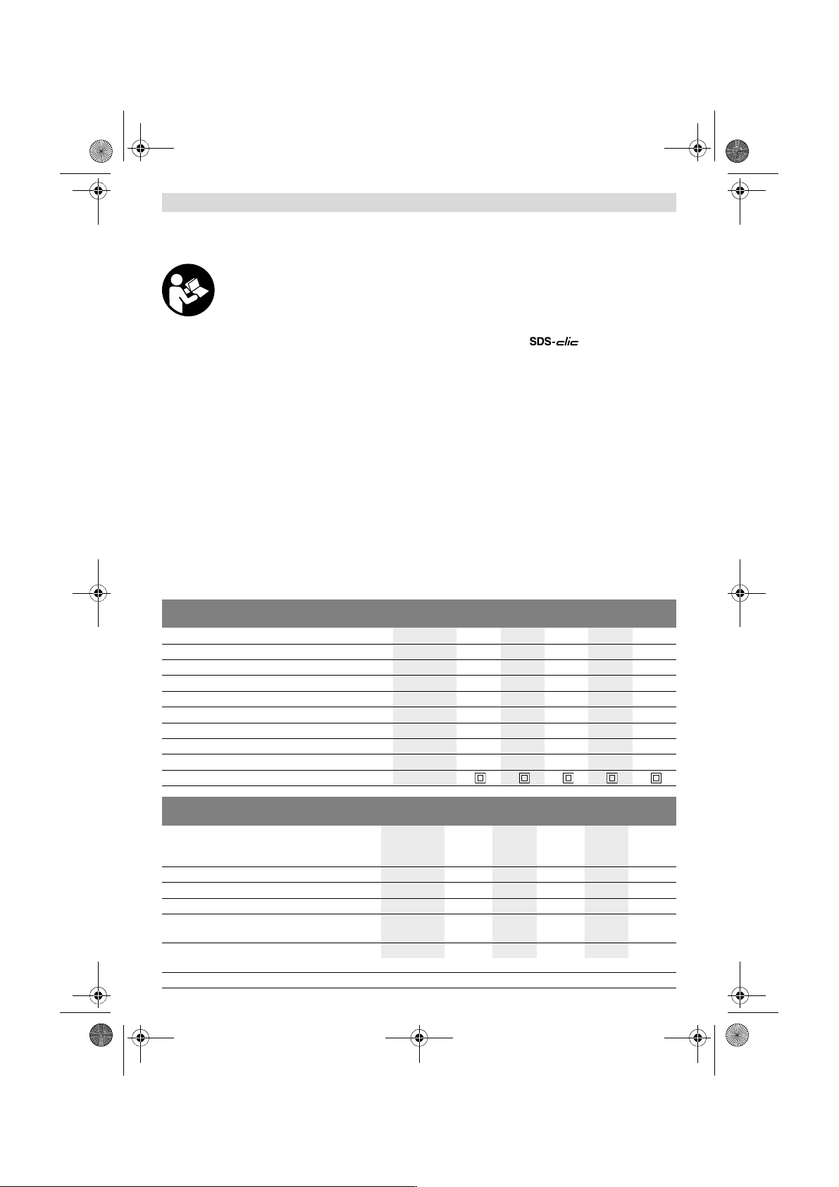
Technical Data
Angle Grinder GWS...
Professional
5-100 580 5-115 670 6-100
Article number 0 601 ... 376 0.. 376 0.. 376 2.. 375 0.. 375 0..
Rated power input
W580580 580 670 670
Output power
W300300 300 400 400
Rated speed
min
-1
11000 11000 11000 11000 11000
Grinding disc diameter, max.
mm 100 100 115 100 100
Thread of grinder spindle
M 10 M 10 M 14 M 10 M 10
Thread length (max.) of grinder spindle
mm 17 17 22 17 17
Speed preselection
– ––––
Weight according to EPTA-Procedure 01:2014
kg 1.8 1.8 1.9 1.8 1.8
Protection class
/II /II /II /II /II
Angle Grinder GWS...
Professional
6-100 E 6-115 6-115 E 6-125 6-125 E
Article number
0 601 ... 375 7.. 375 0.. 375 5..
375 7..
375 9..
375 1.. 375 9..
Rated power input
W 670 670 670 670 670
Output power
W 400 400 400 400 400
Rated speed
min
-1
11000 11000 11000 11000 11000
Speed control adjustment
min
-1
2800
– 11000
– 2800
– 11000
–2800
–11000
Grinding disc diameter, max. mm 100 115 115 125 125
The values given are valid for a nominal voltage [U] of 230 V. For different voltages and models for specific countries, these values can vary.
OBJ_BUCH-704-005.book Page 9 Wednesday, November 23, 2016 10:50 AM
10 | English
1 609 92A 2V9 | (23.11.16) Bosch Power Tools
Assembly
Mounting the Protective Devices
Before any work on the machine itself, pull the mains
plug.
Note: After breakage of the grinding disc during operation or
damage to the holding fixtures on the protection guard/power
tool, the machine must promptly be sent to an after-sales
service agent for maintenance. For addresses, see section
“After-sales Service and Application Service”.
Protection Guard for Grinding
Place the protection guard 8 on the spindle collar. Adapt the
position of the protection guard 8 to the requirements of the
work step. Lock protection guard 8 by tightening locking
screw 9 with combination spanner 5/6.
Adjust the protection guard 8 in such a manner that
sparking is prevented in the direction of the operator.
Note: The encoding keys on the protection guard 8 ensure
that only a protection guard that fits the machine type can be
mounted.
Protection Guard for Cutting
For cutting with bonded abrasives, always use the pro-
tection guard for cutting 15.
Provide for sufficient dust extraction when cutting
stone.
The protection guard for cutting 15 is mounted in the same
manner as the protection guard for grinding 8.
Cutting Guide with Dust Extraction Protection Guard
The cutting guide with dust extraction protection guard 22 is
mounted in the same manner as the protection guard for
grinding 8.
Auxiliary Handle
Operate your machine only with the auxiliary handle 4.
Screw the auxiliary handle 4 on the right or left of the machine
head depending on the working method.
Hand Guard
For operations with the rubber sanding plate 18 or with
the cup brush/wheel brush/flap disc, always mount the
hand guard 17.
The hand guard 17 is fastened with the auxiliary handle 4.
Mounting the Grinding Tools
Before any work on the machine itself, pull the mains
plug.
Do not touch grinding and cutting discs before they
have cooled down. The discs can become very hot while
working.
Clean the grinder spindle 7 and all parts to be mounted.
For clamping and loosening the grinding tools, lock the grind-
er spindle with the spindle lock button 1.
Actuate the spindle lock button only when the grinder
spindle is at a standstill. Otherwise, the machine may be-
come damaged.
Grinding/Cutting Disc
Pay attention to the dimensions of the grinding tools. The
mounting hole diameter must fit the mounting flange without
play. Do not use reducers or adapters.
When using diamond cutting discs, pay attention that the di-
rection-of-rotation arrow on the diamond cutting disc and the
direction of rotation of the machine (see direction-of-rotation
arrow on the machine head) agree.
See graphics page for the mounting sequence.
To fasten the grinding/cutting disc, screw on the clamping nut
12 and tighten it with the combination spanner 5/6, (see sec-
tion “Quick-clamping Nut”).
After mounting the grinding tool and before switching
on, check that the grinding tool is correctly mounted
and that it can turn freely. Make sure that the grinding
tool does not graze against the protection guard or oth-
er parts.
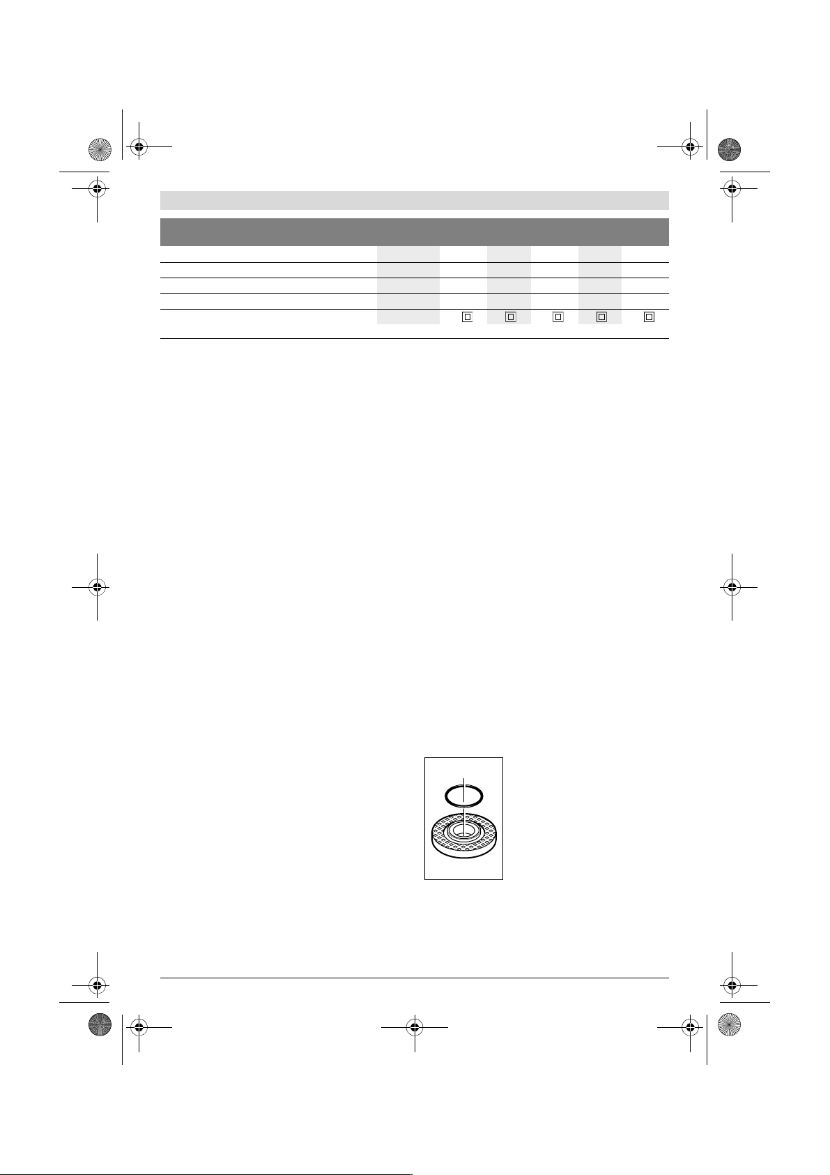
Mounting flange for grinding spindle
M 14: A plastic part (O-ring) is fitted
around the centring collar of mounting
flange 10. If the O-ring is missing or
damaged, the mounting flange 10
must be replaced before resuming op-
eration.
Mounting flange for grinding spindle
M 10: The mounting flange can be used
on both sides.
Flap Disc
For operations with the flap disc, always mount the
hand guard 17.
Thread of grinder spindle
M 10 M 14 M 14 M 14 M 14
Thread length (max.) of grinder spindle
mm 17 22 22 22 22
Speed preselection
– –
Weight according to EPTA-Procedure 01:2014
kg 1.8 1.9 1.9 1.9 1.9
Protection class
/II /II /II /II /II
Angle Grinder GWS...
Professional
6-100 E 6-115 6-115 E 6-125 6-125 E
The values given are valid for a nominal voltage [U] of 230 V. For different voltages and models for specific countries, these values can vary.
OBJ_BUCH-704-005.book Page 10 Wednesday, November 23, 2016 10:50 AM