00198238-01_VD_SIPLACE_Pro_14.0_R16-2_DE_EN.pdf - 第14页
SIPLACE Pro 14.0 (R 16 - 2) / V ersion Description 12/2016 Edition 14 If the previous ma chine is a SIPLACE pl acement machine, the convey or settings of this ma chine will be automatically used as default . For the outp…
SIPLACE Pro 14.0 (R16-2) / Version Description 12/2016 Edition
13
4 Features of SIPLACE Pro 14.0
If not differently described, the features of the previous SIPLACE Pro versions are contained in
SIPLACE Pro 14.0. The main features of SIPLACE Pro 14.0 are listed below.
NOTICE
Detailed information on the individual functions can be found in the Online Help for
SIPLACE Pro.
4.1 SIPLACE TX micron – New Placement Machine
The new SIPLACE TX micron placement machine supports high precision placement on a dual
lane conveyor system. The placement machine exists in two variants: TX2 micron and TX2i
micron. The C&P20 M2 and CPP placement heads and the SIPLACE JTF-ML feeder are
supported. A special vacuum tooling is optionally used to meet the highest accuracy requirements.
A new measuring procedure offers features to increase the accuracy and make the placement
results long time stable. Different precisions are supported.
The desired precision has to be specified for the component shape in SIPLACE Pro. In the
Component Shape Editor, the user has to enable the High entry in the Placement Accuracy field
and enter or select a value in [µm] to specify the required accuracy. The dispersion is fixed to 3 σ
and cannot be changed.
If an accuracy < 20 µm has been specified, the Micron 15u3Sigma – Machine Connection license
is required at the station.
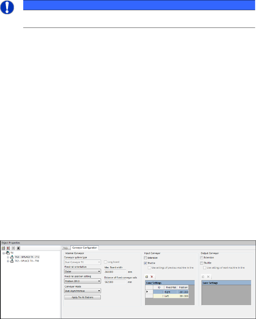
4.2 Shuttle Extension for SIPLACE TX-Series
To reach the best possible output, shuttles might be required in the SIPLACE line, e.g. when
I-Placement mode is used. For this, the new Shuttle Extension has been introduced for the
SIPLACE TX-series. One machine can have up to two shuttle extensions attached – one input
shuttle and one output shuttle.
The shuttle extension itself and its lane settings has to be configured in the Stations of Line tab of
the Line Editor.
Figure 4-1: Line Editor – Stations of Line tab
For the input shuttle it can be configured where the rails of the shuttle extension should align with
the previous machine. This is done by editing the fixed rail orientation (left / right) and the position
of the fixed rail for each lane. Only fixed rail settings left or right of each lane are supported.
SIPLACE Pro 14.0 (R16-2) / Version Description 12/2016 Edition
14
If the previous machine is a SIPLACE placement machine, the conveyor settings of this machine
will be automatically used as default.
For the output shuttle the same configurations are possible in order to match the lanes of the next
machine in the line.
In case the previous / next machine is a 3
rd
party device, the user can configure the settings of the
conveyor manually.
Detailed information on the shuttle extension can be found in the Shuttle Extension Assembly
Instructions and User Manual, item no. [00198271-xx].
4.3 Alternative Component Shapes
Alternative component shapes can now be defined for a component in the Component Editor. In
the new Alternative Component Shapes tab, the alternative component shape can be enabled at
the station. Additionally, this tab contains a list of all possible component shapes of this component
with their selection rule descriptions and a field for the selection which module can switch among
the listed component shapes.
Detailed information can be found in the Alternative Component Shapes User Manual,
item no. [00198270-xx].
4.4 Selecting Fiducial Processing Algorithm
As default, the station decides which algorithm is to be used for computing the board warpage
based on the fiducial measurements. As of SIPLACE Pro 14.0 and station software version 710.0,
the user can select between the default and two further algorithms:
– Standard (station decides, as in previous SIPLACE Pro versions)
– Maximal degrees of freedom (new)
– Rigid body (new)
If Rigid body is selected, a warning is displayed because this setting does not consider the
distortion of the board when components are placed.
The selection is available in the Board Editor for each Board Side and Panel and in the Grid Board
Editor for each Grid Board and Grid Panel Type.
4.5 Odd Shape Components – OSC Package Option
SIPLACE Pro supports a bundle of new features for odd shape components (OSC) as of version
14.0. These features have been collected into the OSC Package option. This option has to be
enabled in SIPLACE Pro for the station(s) concerned under Installed Options – OSC Package.
The option requires the Vision OSC Package - Machine Connection floating license. The license
must be available at download if any of the supported features shall be used.
SIPLACE Pro 14.0 (R16-2) / Version Description 12/2016 Edition
15
Following features are supported by the OSC Package option:
● Vision OSC measuring options:
– User-defined "Odd shape component"
– Stereo measurement for pins (SIPLACE Vision feature only)
– Special position evaluation – "Alignment" attribute
● Increased placement force of Twin VHF placement head to 100 N
● Improved placement of snap-in components
– Specification of Z-threshold
● Support to find best acceleration (station feature only)
The single features which are relevant for SIPLACE Pro are presented in the following sections.
4.5.1 Vision OSC Measuring Options
The new Odd Shape Component setting has been added to the component shape in the Vision
Inspection tab of the Component Shape Editor.
User-defined Odd shape component
The new Pattern Feature lead group type allows the user to describe arbitrary abstract patterns on
a component. These patterns can only be created and changed in the SIPLACE Vision Editor
during teaching at the station.
In SIPLACE Pro, a lead group of this type can be renamed and deleted in the Lead Group tab of
the Component Shape Editor. The Copy lead group option is not possible for this lead group
type. The number of leads in such a group is always one.
Special Position Evaluation
For this feature, the new Alignment attribute has been added to the lead group description of the
component shape in SIPLACE Pro. This attribute is only visible in SIPLACE Vision.
4.5.2 Increased Placement Force of Twin VHF
The placement force has been increased from 70 N to 100 N for the Twin VHF placement head
with item no. [03096701-03]. The cool down time calculation has been adapted for the new range
from 70 N up to 100 N.
Placements with a force greater than 70 N are not supported on stations with software versions
< 710 and Twin VHF placement heads with a functional status < [03]. Such placements will be
forced onto stations with station software version >= 710 by SIPLACE Pro.