00196429-0102 - AI Head Reconfiguration Kit SX12 C&P20A_de_en.pdf - 第44页
Brief Description Head Modularity SX 70x SIPLACE SX 1 44 Assembly Instructions / Mont ageanleitung Head Reconfiguratio n Kit C&P20A Head Modula rity SX 7 0x 2.4 Head Modularity SX 70x The following head configur atio…

Brief Description
Reconfiguration Duration Requirements and Restrictions for the C&P20A Placement Head
Assembly Instructions / Montageanleitung Head Reconfiguration Kit C&P20A 43
Requirements and Restrictions for the C&P20A Placement Head
2.3 Requirements and Restrictions for the C&P20A Placement Head
▪ When using third party feeder modules pay particular attention on the crash danger.
▪ In a placement area with 2 gantries the C&P20A can only be operated together with another C&P20A
placement head.
▪ The C&P20A cannot be operated with an MTC2 in the same placement area.
▪ Only use the nozzle changers and camera types appropriate for this head type as well as the elec-
trical boards described in this manual. Remove all boards that do not belong to this head type. Oth-
erwise there is the danger of a crash.
▪ When using a C&P20A head no magazines of the CPP head are allowed on the nozzle changer. For
the new basic unit for nozzle changers, this is monitored by the software. The new basic unit is suited
for the nozzle changer magazines of the CPP head and the C&P20A head.
▪ Do not use a linear feeder together with a C&P20A placement head.
Reconfiguration Duration
2.3.1 Reconfiguration Duration
The following reconfiguration durations per head can be expected:
Placement head Single-/Double conveyor Task
Disassembling CPP 20 min Without options such as nozzle changers, verify
component reject bin and stationary camera
Disassembling
C&P20A
20 min Without options such as nozzle changer, verify
component reject bin
Disassembling Twin-
Head
30 min Verify Component reject bin
Assembling CPP 90 / 120 min With mapping and without options such as nozzle
changer, verify component reject bin and stationary
camera
Assembling C&P20A 90 / 120 min With mapping and without options such as nozzle
changer, query component reject bin
Assembling Twin-
Head
90 / 120 min With mapping and without options such as nozzle
changer, verify component reject bin and stationary
camera

Brief Description
Head Modularity SX 70x SIPLACE SX 1
44 Assembly Instructions / Montageanleitung Head Reconfiguration Kit C&P20A
Head Modularity SX 70x
2.4 Head Modularity SX 70x
The following head configuration options are available:
SIPLACE SX 1
2.4.1 SIPLACE SX 1
Head configurations on the SIPLACE SX 1
SIPLACE SX 2
2.4.2 SIPLACE SX 2
Head configurations on the SIPLACE SX 2
Gantry 1 Default cameras Options
C&P20A STT 23 ----
CPP_H SST 29 Component camera SST 38
Stat. camera SST 33 (from FS 04 and in low installation posi-
tion only)
CPP_L SST 29 Component camera SST38
TwinHead SST 33 Stat. camera SST 25 (location 1 only)
3D coplanarity module ST 37 (location 1 only)
Gantry 1 / Gantry 2 Default cameras Options
C&P20A / C&P20A STT 23 ----
CPP_H / CPP_H SST 29 Component camera SST 38
Stat. camera SST 33 possible on location 1 and
2 (from FS 04 and in low installation position on-
ly)
CPP_L / CPP_L SST 29 Component camera SST38
CPP_H / TwinHead STT 29 (on gan-
try 1)
Twin SST33 (on
gantry 2)
CPP:
Component camera SST 38
Stat. camera SST 33 (from FS 04 and in low in-
stallation position only)
TwinHead:
Stat. camera SST 25 (location 1 only)
3D coplanarity module SST 37 (location 1 only)
TwinHead / TwinHead SST 33 Stat. camera SST 25 (location 1 only)
3D coplanarity module ST 37 (location 1 only)
Brief Description
Disassembly Sequence Sequence of the Placement Head Exchange
Assembly Instructions / Montageanleitung Head Reconfiguration Kit C&P20A 45
Sequence of the Placement Head Exchange
2.5 Sequence of the Placement Head Exchange
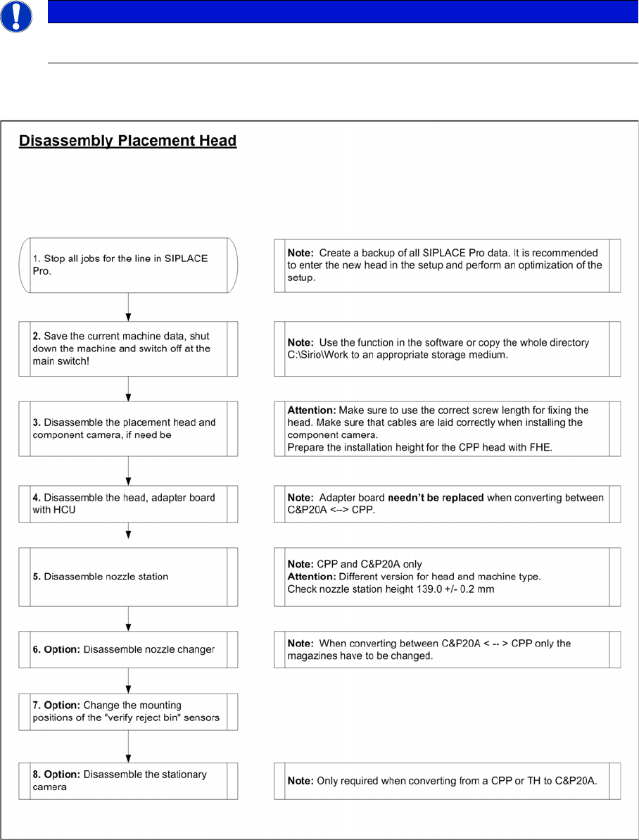
Disassembly Sequence
2.5.1 Disassembly Sequence
NOTICE
The flow charts describe the general procedure for switching between different placement head
types on SX1/2 machines from SW70x.