00196429-0102 - AI Head Reconfiguration Kit SX12 C&P20A_de_en.pdf - 第57页
Installing the C&P20A Placement Head Height Adjustment and Installatio n of the Nozzle Station Assembl y of the C&P20A Placement Head Assembly Instructions / Montageanleitung Head Reconfiguration K it C&P20A …
Installing the C&P20A Placement Head
Assembly of the C&P20A Placement Head Height Adjustment and Installation of the Nozzle Station
56 Assembly Instructions / Montageanleitung Head Reconfiguration Kit C&P20A
Installing the Nozzle Station
3.4.3.2 Installing the Nozzle Station
► Remove the downholder on the right above the reject bin.
► Fasten the downholder left [03079173-xx] above the reject bin [03048638-xx] (see "3.4.3.3.2 Install-
ing/Removing Downholder" [ ➙ 58]).
► Insert the coding sheet at unoccupied bin locations [03083883-xx] (see "3.4.3.3.3 Installing/Remov-
ing Coding Sheet" [ ➙ 59]).
► Install the valve for the nozzle station [03055785-xx] (4) at the COT insert using the two DIN912-
M2,5 x 16-A2-70 screws [00350291-xx].
► Replace, unless already performed, the QSC-6H plug at the solenoid valve feed control with the Y
press-fit connection with push-on socket QSY-6H-4 [03055792-xx].
► Plug the hose PUN-CM 4x0.75 / 200mm [03056096-xx] into the pneumatic connection to the nozzle
changer (5) and into the pneumatic connection of the nozzle changer (6) or close it with the plug
QSC-4H [00330249-xx].
► Plug the hose PUN-CM 4x0.75 / 135mm [03056097-xx] into the pneumatic connection to the nozzle
changer [03055785-xx] (3) and to the pneumatic connection of the nozzle changer (2).
► Connect the cable "Cable feed X series: nozzle station" [03053223-xx] which has already been con-
nected in the COT insert with the "valve for nozzle station cplt." [03055785-xx].
► If the verify reject bin option is already installed, the sensor for this reject bin has to be installed at
another position. For this, use the metal sensor MK2 prefitted (reject bin 6x6) [03080138-xx]. For fur-
ther information please refer to the Assembly Instructions Reject Bin SIPLACE SX1/2 [00196615-
xx].
See also
3.4.3.3 Installing the Downholder and the Coding Sheet [ ➙ 57]
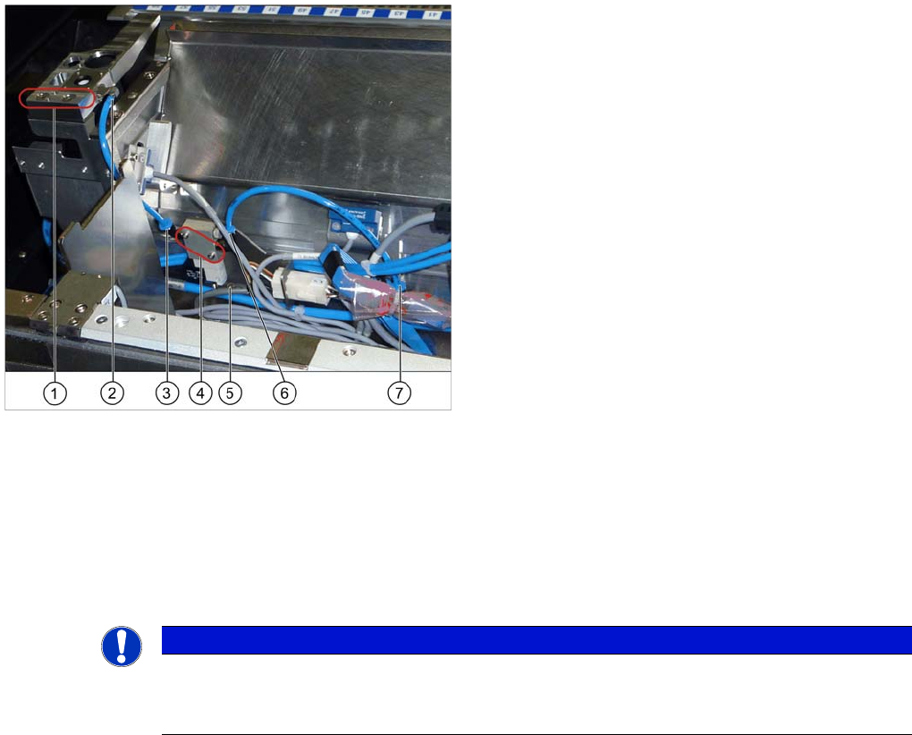
Installing the nozzle station
1. Fixation points of the nozzle station [03073328-xx]
2. Pneumatic connection on the nozzle station
3. Pneumatic connection to the nozzle station
4. Valve for the nozzle station [03055785-xx]
5. Pneumatic connection to the nozzle changer
6. Fixing screw of the mounting plate
7. Pneumatic connection on the nozzle changer
► Fit the nozzle station [03073328-xx] with two screws
in its mounting position (1).
► Depending on the machine configuration (see
"3.4.3.3.1 Configurations with Reject Bins and Cod-
ing Sheet" [➙ 57]) insert the reject bin [03048638-xx]
and the component reject bin up to 6x6 [03062378--
xx]. The reject bin mustn't be higher than the convey-
or side wall in any case.
NOTICE
The mounting plate for the solenoid valve is fastened and fixed in position with one screw only
(6). If necessary, loosen this mounting plate to install the solenoid valve.
Attention: the connector left to the solenoid valve is also fastened to this plate.
Installing the C&P20A Placement Head
Height Adjustment and Installation of the Nozzle Station Assembly of the C&P20A Placement Head
Assembly Instructions / Montageanleitung Head Reconfiguration Kit C&P20A 57
Installing the Downholder and the Coding Sheet
3.4.3.3 Installing the Downholder and the Coding Sheet
Depending on the configuration of the SX machine either the reject bin [03063238-xx] with downholder
[03079173-xx] or the component reject bin up to 6x6 [03062378--xx] is used on occupied box locations.
On unoccupied bin locations the coding sheet (No Box) [03083883-xx] has to be installed.
For the description of the configurations refer to "3.4.3.3.1 Configurations with Reject Bins and Coding
Sheet" [ ➙ 57].
For the description of the installation and the removal refer to "3.4.3.3.2 Installing/Removing Downhold-
er" [ ➙ 58] and "3.4.3.3.3 Installing/Removing Coding Sheet" [ ➙ 59].
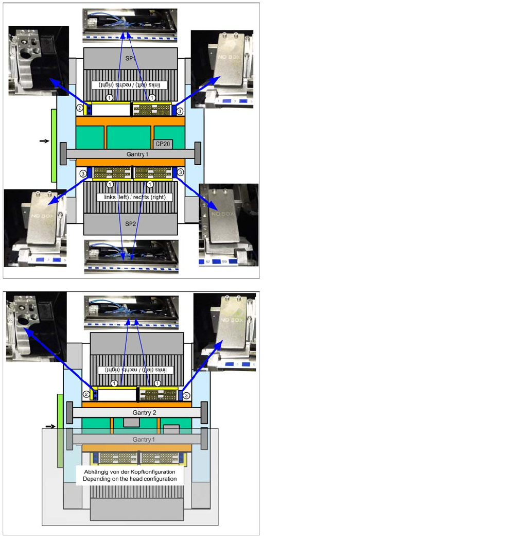
Configura tions with Reject Bins and Coding S heet
Configurations with Reject Bins and Coding Sheet
SX 1
Nozzle station in SP1 right, component reject bin up to
6x6 [03062378--xx] in SP1 and 2, coding sheet in SP1 left
as well as in SP2 left and right
SX2
Nozzle station right, component reject bin up to 6x6
[03062378--xx], coding sheet left
On the other gantry: depending on the head configura-
tion.
Installing the C&P20A Placement Head
Assembly of the C&P20A Placement Head Height Adjustment and Installation of the Nozzle Station
58 Assembly Instructions / Montageanleitung Head Reconfiguration Kit C&P20A
Installing/Removing Downholder
Installing/Removing Downholder
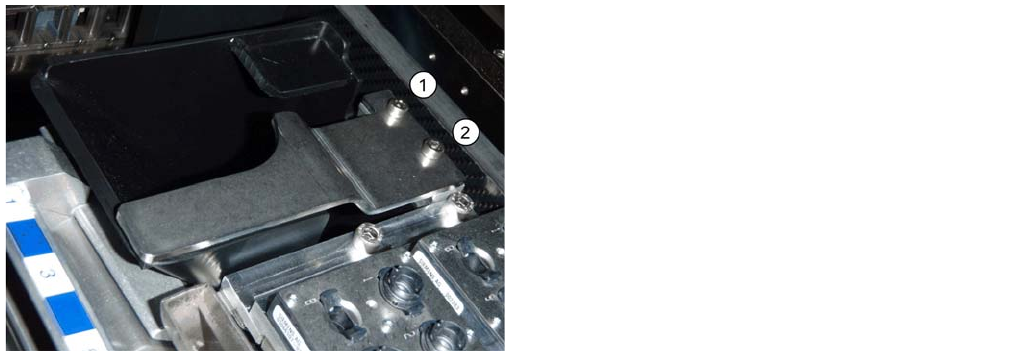
Installing downholder
Removing downholder
When exchanging the placement head type it may be necessary, depending on the new configuration,
to remove downholders and reject bins and replace them by coding sheets on unopccupied bin locations.
The configurations with reject bins, downholders and coding sheets are described in the relevant assem-
bly instructions ([00196429--xx] for changeover to C&P20A, [00196430-xx] for changeover to CPP and
[00196431--xx] changeover to TwinHead).
► Remove the two screws (1 and 2) and lift off the downholder.
► Remove the reject bin.
► Insert the reject bin [03063238-xx].
► Fasten the downholder [03079173-xx] directly on the
cast part of the used tape channel using two screws
(1 and 2).
No shim plates are required.