00196429-0102 - AI Head Reconfiguration Kit SX12 C&P20A_de_en.pdf - 第61页
Installing the C&P20A Placement Head Connections on the Hotlink Card (Box PC) Assembly of the C&P20A Placement Head Assembly Instructions / Montageanleitung Head Reconfiguration K it C&P20A 61 Connecti ons on…
Installing the C&P20A Placement Head
Assembly of the C&P20A Placement Head Settings On the Base Adapter
60 Assembly Instructions / Montageanleitung Head Reconfiguration Kit C&P20A
Settings On the Ba se Adapter
3.4.4 Settings On the Base Adapter
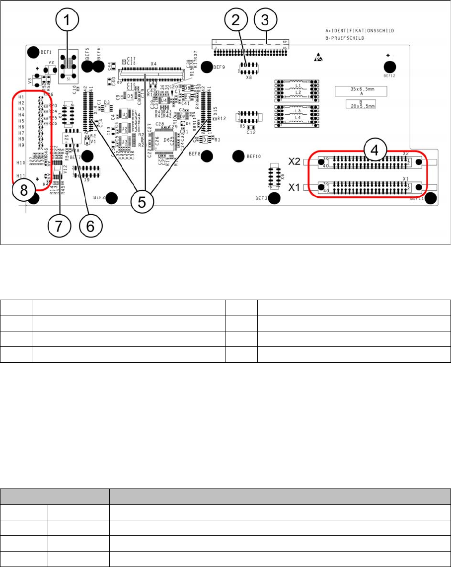
Base adapter for CPP and C&P20A heads (without HCU)
Legend
Switch S1
This switch sets the intermediate circuit voltage for the Z axis.
▪ The switch must be set to 40 V for C&P20 heads.
▪ The setting must be 150 V for CPP heads.
If the setting is incorrect, no damage will be done but an HCU error message will be issued.
DIP switch S2
All switches must be set to OFF. The HCU can be reset with S3, if necessary.
1 Switch S1 (see below) 2 X4 – for checking the voltages
3 Connection to the head interface C700 4 X1 and X2 – to the head
5 X4, X14 and X15 – for the HCU 6 DIP switch S2
7 7 segment display 8 LEDs H1-H11
Switches Description
S1 S0 Gantry encoding (currently not in use)
S2 S1 Gantry encoding (currently not in use)
S3 Reset Reset HCU
S4 Boot Activation of bootstrap function for the HCU (not designed for Service)
Installing the C&P20A Placement Head
Connections on the Hotlink Card (Box PC) Assembly of the C&P20A Placement Head
Assembly Instructions / Montageanleitung Head Reconfiguration Kit C&P20A 61
Connecti ons on the Hotlink Card (B ox PC)
3.4.5 Connections on the Hotlink Card (Box PC)
► Insert a USB stick or another appropriate storage medium into the USB slot of the station computer.
► Save the machine data from the storage medium to the station computer.
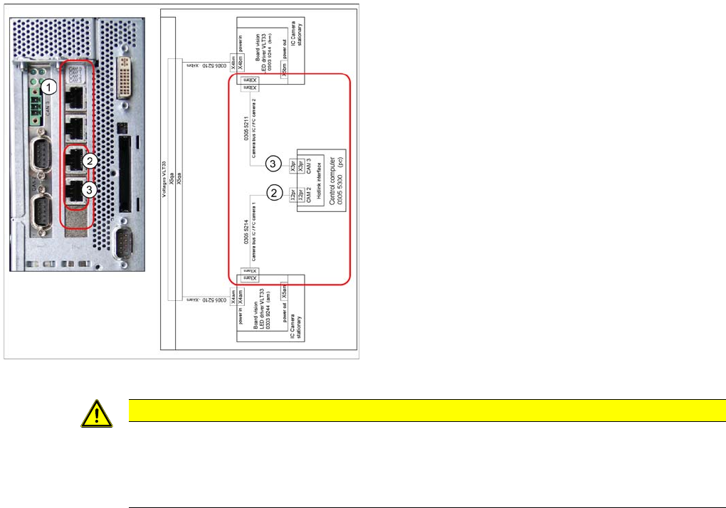
Connections on the hotlink card
Legend
1. Hotlink connections CAM 0 to CAM 3 at the BOX PC.
2. CAM 2 - X2pr
03055214: stationary IC / FC camera 1
3. CAM 3 - X3pr
03055211: stationary IC / FC camera 2
► Plug in the Hotlink cable for the relevant component
camera.
CAUTION
The Hotlink cables of the IC and FC cameras must be unplugged for the placement area in
which there is a C&P20A or a CPP head if no stationary camera is used here.
Do not connect the Hotlink cables which are not in use!
Do not confuse the Hotlink cables with the twisted pair cables!
Installing the C&P20A Placement Head
Installation and Removal of Options Option Nozzle Changer
62 Assembly Instructions / Montageanleitung Head Reconfiguration Kit C&P20A
Installation and Removal of Options
3.5 Installation and Removal of Options
Option Nozzle Changer
3.5.1 Option Nozzle Changer
► When replacing the TwinHead by a C&P20A/CPP head the nozzle changer of the TwinHead must
be replaced by the appropriate nozzle changer for the C&P20A/CPP head.
► For installing and removing the nozzle changer please refer to the Assemby Instruction "Nozzle
Changer SX1/2" [00196432-xx].
Option Verify Reject Bin
3.5.2 Option Verify Reject Bin
► For installing and removing the option Verify component reject bin please refer to the Assembly In-
structions "Reject Bin SX1/2" [00196615-xx].
Final Work
3.6 Final Work
► Switch the placement machine on at the main switch.
The head exchange will be indicated after the startup of the machine.
► Confirm the new configuration.
► Check the firmware version for the placement head and the HCU and perform a download, if needed.
► Apply the data (zero point correction star and Z axis) from the placement head.
► If the placement head is installed on a machine for the first time, it does not contain any calibration
data.
► Calibrate the placement head.
If the placement head has already been used on another machine, you can use the calibration data
from the memory of the placement head.
► Measure the nozzle changers and, if necessary, the stationary camera.
► Perform the mapping procedure if necessary.
► Perform another restart.
The conversion is completed with that.
CAUTION
Crash danger
Operate a placement head with its appropriate nozzle changer only. There is crash danger
when using a wrong nozzle changer.
NOTICE
If a second nozzle changer row is retrofitted, it may be necessary to loosen the COT insert and
move it outwards. Read the applicable service manual for this. After completion of work, this
needs to be fixed into place again and all attached parts (nozzle changer) must be remeasured.