00193411-02.pdf - 第103页
User Manual SIPLAC E HS-60 4 Setting up the placement system Software vers ion SR.503.xx 07/2003 US Edit ion 4.2 Setting up the plac ement system 103 3 x 16 A for 3 x 380 V AC 4 3 x 16 A for 3 x 400 V AC 4 3 x 16 A for 3…

4 Setting up the placement system User Manual SIPLACE HS-60
4.1 Transport dimensions Software version SR.503.xx 07/2003 US Edition
102
4.1.1 Transport configuration and transportation
The following components are not installed when the placement system is delivered from the fac-
tory:
– keyboards
–monitors
– fault indicator lamp and
– component trolley
Æ Install the dismantled components for commissioning.
Æ Use a fork-lift truck to transport the placement system:
– minimum fork length 2000 mm if the mounting kit is dismantled.
– minimum fork length 2500 mm if the mounting kit is dismantled.
Æ Attach the fork-lift truck only at the indicated points.
4.1.2 Quality of the foundation
Æ Ensure that
– you set up the placement system on a firm and non-vibrating foundation.
– the load bearing capacity per unit area of the foundation is greater than 1000 kg/m².
4.1.3 Compressed air supply
– The pressure of the compressed air supply must be between 0.65 MPa and 1.0 MPa (6.5 bar
and 10 bar).
– The compressed air must conform to the specification (see Section 3.4
from page 79).
This can be achieved with
– oil-free compressors, e.g. Atlas, Copco type ZR4
– compressed air washer/driers
– micro-filters, series X, e.g. from Zander
4.1.4 Main power supply
– The power socket must be fused. The fuse ratings are:
3x32A for 3x204VAC 4
3x32A for 3x230VAC 4
User Manual SIPLACE HS-60 4 Setting up the placement system
Software version SR.503.xx 07/2003 US Edition 4.2 Setting up the placement system
103
3 x 16 A for 3 x 380 VAC 4
3 x 16 A for 3 x 400 VAC 4
3 x 16 A for 3 x 415 VAC 4
4
4
4.2 Setting up the placement system
Æ Raise the placement system using the fork-lift truck and adjust the feet until there is a gap of
830 mm (950 mm SMEMA height) between the top edge of the PCB conveyors and the bot-
tom edge of the feet.
Æ Leave a gap of 1 to 3 mm between the PCB conveyors of the placement system.
Æ Align all the placement systems exactly in line with one another. Use a cord pulled tight to en-
sure this.
Æ Adjust each placement system using a spirit level with an accuracy of 0.02 mm/m.
Æ Lock the feet in position.
Æ Check the placement system again using the spirit level and correct the settings, if necessary.
CAUTION
Make sure that you remove all the shipping braces from the placement system. 4
Æ Fit any components that were dismantled for dispatch.
Æ Connect all the electrical and pneumatic lines.
RISK OF DEATH
The electrical connection work MUST be carried out only by appropriately trained and cer-
tified personnel. 4
4 Setting up the placement system User Manual SIPLACE HS-60
4.3 Converting the component trolley for other PCB transport heights Software version SR.503.xx 07/2003 US Edition
104
4.3 Converting the component trolley for other PCB
transport heights
4.3.1 Tools
Allen key, set up to 8 mm
4.3.2 Safety instructions
WARNING DANGER OF CRUSHING 4
Remove all the feeders from the table bed before you change the height of the table on the com-
ponent trolley. Take care during the conversion work because the table bed is very heavy. 4
4
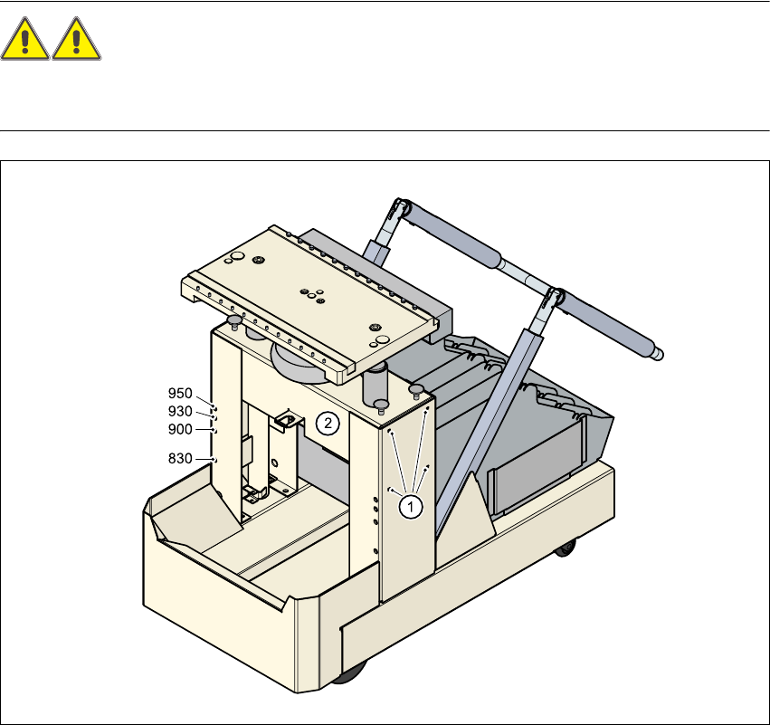
Fig. 4.3 - 1 Converting the component trolley for another PCB transport height
(1) Clamping screws, 4 on each side
(2) Holes in the cross-beam for setting the table height to 830, 900, 930 and 950 mm