00193411-02.pdf - 第48页
2 Operational safety User Manual SIPLACE HS-60 2.5 Safety equipment Software version SR. 503.xx 07/2003 US Edition 48 2.5.3.2 Position of EMERGENCY -STOP-button, circuit breaker s etc. on the machine 2 Fig. 2.5 - 5 EMER …
User Manual SIPLACE HS-60 2 Operational safety
Software version SR.503.xx 07/2003 US Edition 2.5 Safety equipment
47
2.5.3 Main power switch, EMERGENCY-STOP-button, protective cover switch
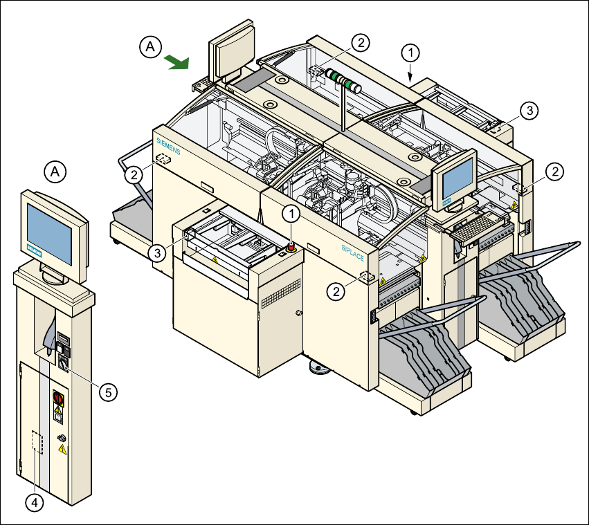
2.5.3.1 Position of the main power switch, start buttons etc. on the machine
2
Fig. 2.5 - 4 Position of main switch, start buttons etc.
2
(1) Main power switch
(2) Stop button (black)
(3) Start button (white)
(4) Component counter
(5) Service socket in the power supply unit behind the safety door
2 Operational safety User Manual SIPLACE HS-60
2.5 Safety equipment Software version SR.503.xx 07/2003 US Edition
48
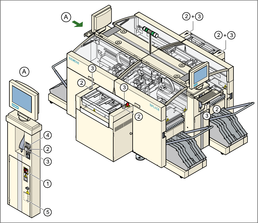
2.5.3.2 Position of EMERGENCY-STOP-button, circuit breakers etc. on the machine
2
Fig. 2.5 - 5 EMERGENCY-STOP-button, circuit-breaker
2
(1) Emergency stop button
(2) Protective cover switch
(3) Cover switches over the PCB conveyors
(4) Protective contactor combination in the power supply unit behind the safety door
(5) Key switch
Key switch open: Position 0 for normal operation
Key switch closed: Position I for service purposes
User Manual SIPLACE HS-60 2 Operational safety
Software version SR.503.xx 07/2003 US Edition 2.5 Safety equipment
49
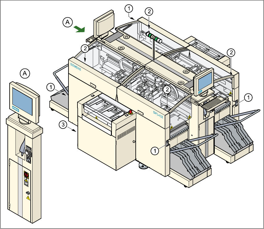
2.5.3.3 Position of UPS, station computer and sockets for connecting the CO trolleys
2
Fig. 2.5 - 6 UPS, station computer, sockets for connecting the CO-trolley
2
(1) Socket for connecting the CO trolley
(2) Push-button for raising the component trolley, with the cover flap over it
(3) UPS and station computer