00193411-02.pdf - 第166页
7 Station extensions User Manual SIPLACE HS-60 7.4 PCB barcode Software version SR.503.xx 07/2003 US Edition 166 7.4.4 Assembly options fo r the PCB barcode reader Fig. 7.4 - 3 Assembly options for the PCB barcode reader…

User Manual SIPLACE HS-60 7 Station extensions
Software version SR.503.xx 07/2003 US Edition 7.4 PCB barcode
165
7
* This value can only be achieved if the barcode label on the PCB passes through the scanner
perpendicular to the machine’s transport direction.
** The position of the barcode reader on the input conveyor can be easily adjusted, depending
on where the barcode labels are located on the PCBs.
Code types Code 39, Code 128 / EAN 128,
Codabar, 2/5 IATA 2/5 industrial,
2/5 interleaved, UPC, EAN,
Pharma Code, EAN Addendum
(others available upon request)
Complete barcode Up to 25 digits (a barcode filter can also be defined)
Laser scanner safety Laser diode 670 nm (red) / 1.2 mW
Laser protection class 2, type of protection IP65
Station and line software Version 502.xx or later
Scanning / analysis duration Time neutral (T ≤ 1 s), since it is carried out in parallel
to placement of the previous PCB
7 Station extensions User Manual SIPLACE HS-60
7.4 PCB barcode Software version SR.503.xx 07/2003 US Edition
166
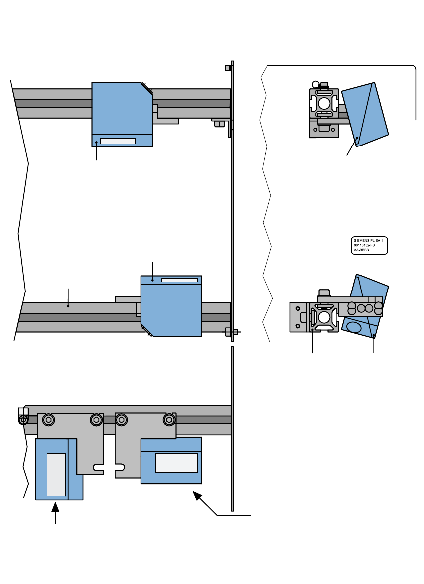
7.4.4 Assembly options for the PCB barcode reader
Fig. 7.4 - 3 Assembly options for the PCB barcode reader
Front view Side view
Assembly for
PCB barcode on
the PCB topside
Assembly for
PCB barcode on
the PCB underside
Plan view
Position of the PCB barcode reader
if the barcode strip is aligned parallel to
the PCB transport direction.
Position of the PCB barcode reader
if the barcode strip is aligned perpen-
dicular to the PCB transport direction.
Profiled rail
PCB barcode
reader 'topside'
PCB barcode
reader ‘underside’
Profiled rail

User Manual SIPLACE HS-60 7 Station extensions
Software version SR.503.xx 07/2003 US Edition 7.5 Ceramic substrate centering
167
7.5 Ceramic substrate centering
7.5.1 General
The ceramic substrate can be centered either mechanically or optically.
The position of the fiducials on the ceramic substrates can be detected either with
– the sub-gantry PCB camera with normal lighting that is fitted as standard, or
– using the multi-color PCB camera (option).
7
7.5.2 Mechanical centering
7.5.2.1 General
Mechanical substrate centering is used to lock ceramic substrates firmly in position in the X and
Y directions in such a way that the material is not damaged. Ceramic substrates can be placed
right up to the edge.
7.5.2.2 Assembling and dismantling the ceramic substrate centering unit
PLEASE NOTE
The ceramic substrate centering unit must only be assembled and dismantled by service engi-
neers. 7