PNOZ_X2_8P_Operat_Manual_1004082-EN-21.pdf - 第10页
PNOZ X2.8P Operating Manual PNOZ X2.8P 1004082-EN-21 | 10 Function Description The safety relay PPNOZ X2.8P provides a safety-oriented interruption of a safety circuit. When supply voltage is supplied the "POWER&quo…
PNOZ X2.8P
Operating Manual PNOZ X2.8P
1004082-EN-21
| 9
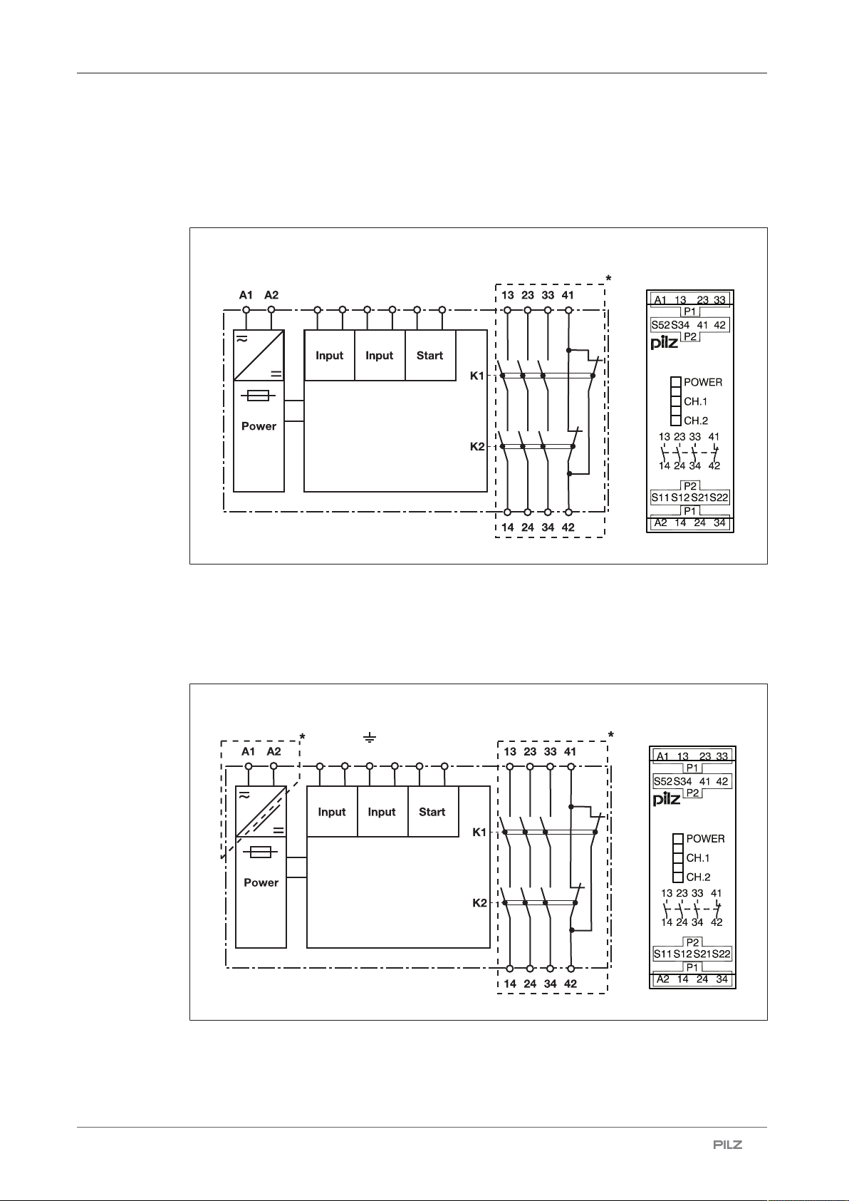
Block diagram/terminal configuration
Type: 24 VAC/DC
} U
B
: 24 VAC/DC; Order no. 777301, 787301
S11 S52 S21 S22 S12 S34
PNOZ X2.8P
*Insulation between the non-marked area and the relay contacts: Basic insulation (over-
voltage category III), Protective separation (overvoltage category II)
Type: 24 - 240 V AC/DC
} U
B
: 24 – 240 VAC/DC; Order no. 777302, 787302
S11 S52 S21 S22 S12 S34
PNOZ X2.8P
*Insulation between the non-marked area and the relay contacts: Basic insulation (over-
voltage category III), Protective separation (overvoltage category II)

PNOZ X2.8P
Operating Manual PNOZ X2.8P
1004082-EN-21
| 10
Function Description
The safety relay PPNOZ X2.8P provides a safety-oriented interruption of a safety circuit.
When supply voltage is supplied the "POWER" LED is lit. The unit is ready for operation
when the start circuit S12-S34 is closed.
} Input circuit is closed (e.g. E-STOP pushbutton not operated):
– LEDs "CH1" and "CH2" will light.
– Safety contacts 13-14, 23-24 and 33-34 are closed, auxiliary contact 41-42 is open.
The unit is active.
} Input circuit is opened (e.g. E-STOP pushbutton operated):
– The LEDs "CH1" and "CH2" go out.
– Safety contacts 13-14, 23-24 and 33-34 are opened redundantly, auxiliary contact
41-42 is closed.
Operating modes
} Single-channel operation: No redundancy in the input circuit, earth faults in the start and
input circuit are detected.
} Dual-channel operation without detection of shorts across contacts: Redundant input cir-
cuit, detects PNOZ X2.8P
– earth faults in the start and input circuit,
– short circuits in the input circuit.
} Dual-channel operation with detection of shorts across contacts: Redundant input circuit,
PNOZ X2.8P detects
– earth faults in the start and input circuit,
– short circuits in the input circuit,
– shorts across contacts in the input circuit.
} Automatic start: Unit is active once the input circuit has been closed.
} Manual start: Unit is active once the input circuit and the start circuit are closed.
} Increase in the number of available contacts by connecting contact expandsion modules
or external contactors/relays.
PNOZ X2.8P
Operating Manual PNOZ X2.8P
1004082-EN-21
| 11
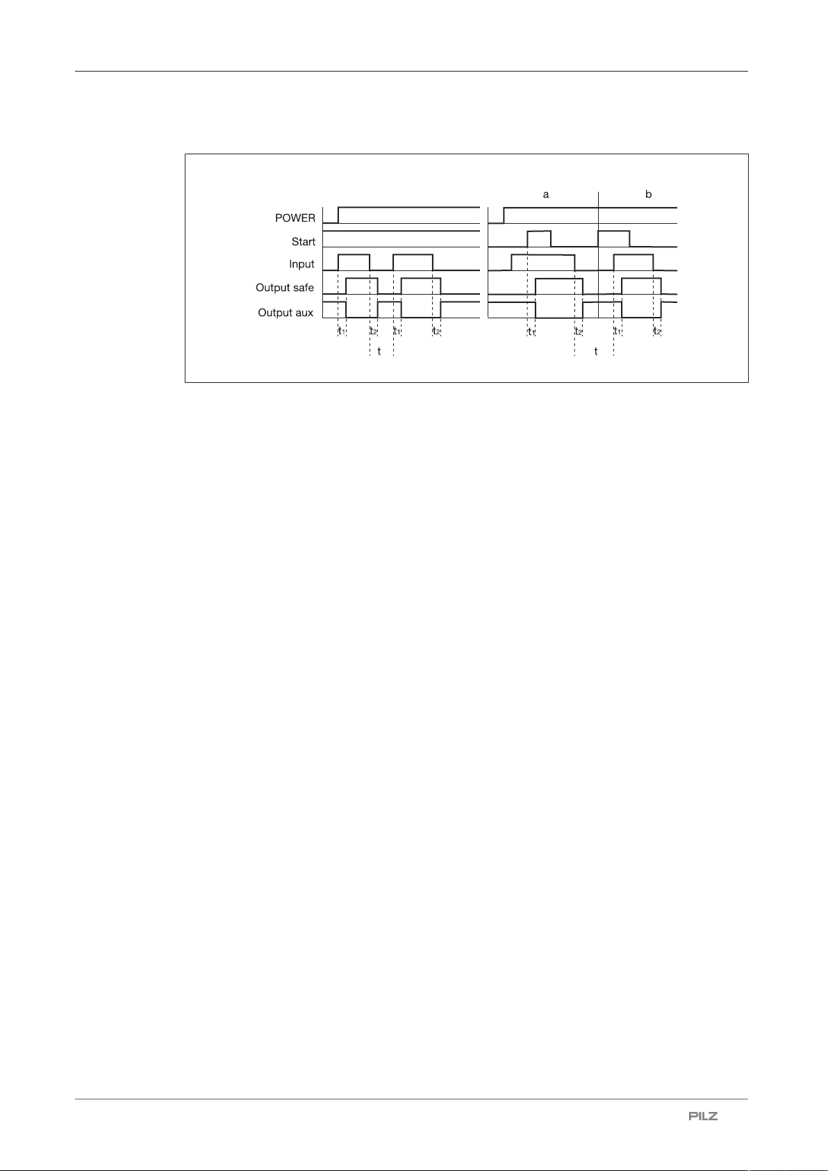
Timing diagram
[1][1] [2][2]
3 3
Legend
} Power: Supply voltage
} Start: Start circuit
} Input: Input circuit
} Output safe: Safety contacts
} Output aux: Auxiliary contact
} [1]: Automatic start
} [2]: Manual start
} a: Input circuit closes before start circuit
} b: Start circuit closes before input circuit
} t
1
: Switch-on delay
} t
2
: Delay-on de-energisation
} t
3
: Recovery time
Installation
} The unit should be installed in a control cabinet with a protection type of at least IP54.
} Use the notch on the rear of the unit to attach it to a DIN rail (35 mm).
} When installed vertically: Secure the unit by using a fixing element (e.g. retaining bracket
or end angle).