PNOZ_X2_8P_Operat_Manual_1004082-EN-21.pdf - 第9页
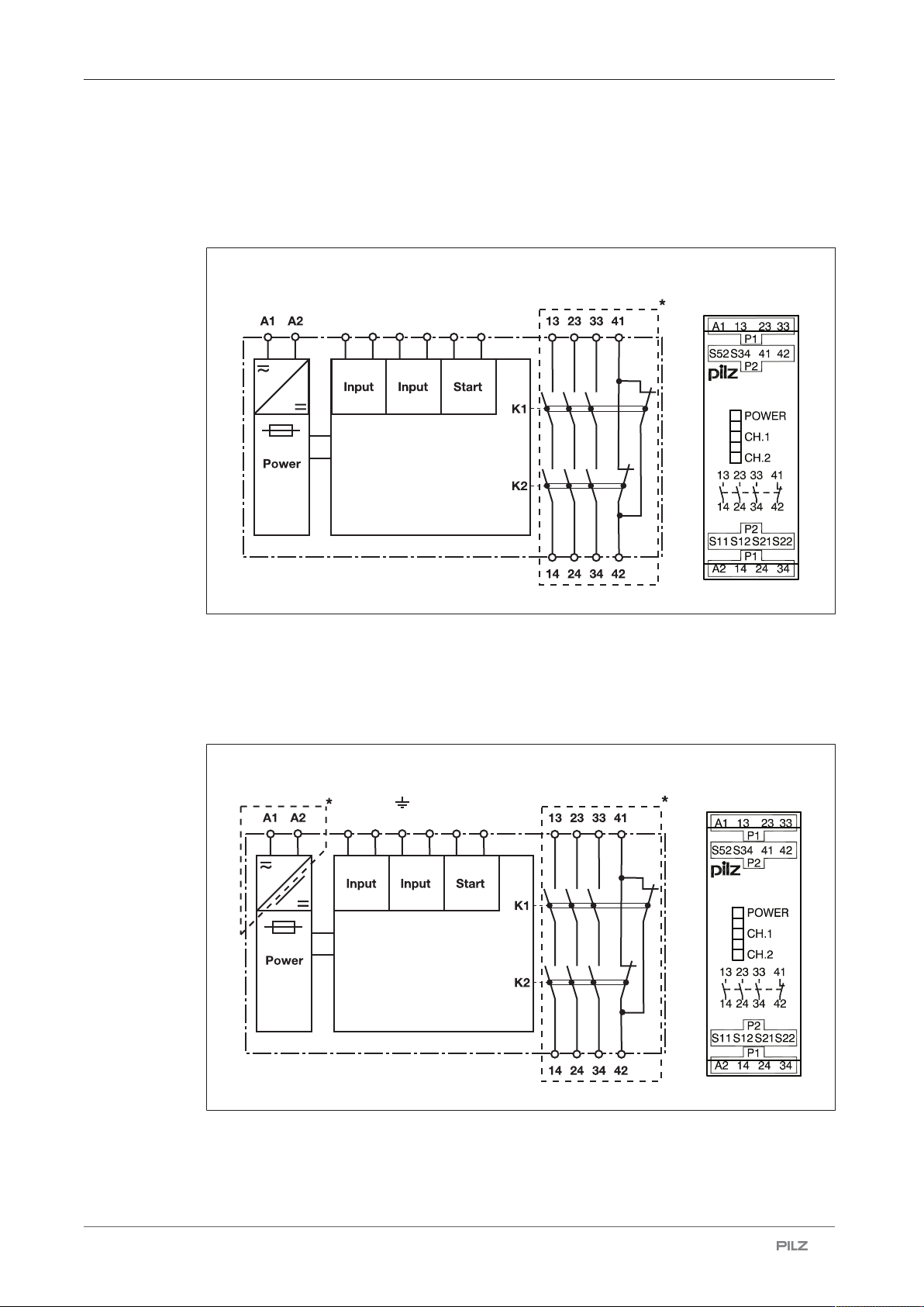
PNOZ X2.8P Operating Manual PNOZ X2.8P 1004082-EN-21 | 9 Block diagram/terminal configuration Type: 24 VAC/DC } U B : 24 VAC/DC; Order no. 777301, 787301 S1 1 S52 S21 S22 S12 S34 PNOZ X2.8P *Insulation between the non-ma…

PNOZ X2.8P
Operating Manual PNOZ X2.8P
1004082-EN-21
| 8
Unit features
} Positive-guided relay outputs:
– 3 safety contacts (N/O), instantaneous
– 1 auxiliary contact (N/C), instantaneous
} Connection options for:
– E-STOP pushbuttons
– Safety gate limit switches
– Start button
– Light guards and safety switches
} LED display for:
– Supply voltage
– Switch status of the safety contacts
} Plug-in connection terminals (either spring-loaded terminal or screw terminal)
} See order reference for unit types
Safety features
The safety relay meets the following safety requirements:
} The circuit is redundant with built-in self-monitoring.
} The safety function remains effective in the case of a component failure.
} The correct opening and closing of the safety function relays is tested automatically in
each on-off cycle.
PNOZ X2.8P
Operating Manual PNOZ X2.8P
1004082-EN-21
| 9
Block diagram/terminal configuration
Type: 24 VAC/DC
} U
B
: 24 VAC/DC; Order no. 777301, 787301
S11 S52 S21 S22 S12 S34
PNOZ X2.8P
*Insulation between the non-marked area and the relay contacts: Basic insulation (over-
voltage category III), Protective separation (overvoltage category II)
Type: 24 - 240 V AC/DC
} U
B
: 24 – 240 VAC/DC; Order no. 777302, 787302
S11 S52 S21 S22 S12 S34
PNOZ X2.8P
*Insulation between the non-marked area and the relay contacts: Basic insulation (over-
voltage category III), Protective separation (overvoltage category II)

PNOZ X2.8P
Operating Manual PNOZ X2.8P
1004082-EN-21
| 10
Function Description
The safety relay PPNOZ X2.8P provides a safety-oriented interruption of a safety circuit.
When supply voltage is supplied the "POWER" LED is lit. The unit is ready for operation
when the start circuit S12-S34 is closed.
} Input circuit is closed (e.g. E-STOP pushbutton not operated):
– LEDs "CH1" and "CH2" will light.
– Safety contacts 13-14, 23-24 and 33-34 are closed, auxiliary contact 41-42 is open.
The unit is active.
} Input circuit is opened (e.g. E-STOP pushbutton operated):
– The LEDs "CH1" and "CH2" go out.
– Safety contacts 13-14, 23-24 and 33-34 are opened redundantly, auxiliary contact
41-42 is closed.
Operating modes
} Single-channel operation: No redundancy in the input circuit, earth faults in the start and
input circuit are detected.
} Dual-channel operation without detection of shorts across contacts: Redundant input cir-
cuit, detects PNOZ X2.8P
– earth faults in the start and input circuit,
– short circuits in the input circuit.
} Dual-channel operation with detection of shorts across contacts: Redundant input circuit,
PNOZ X2.8P detects
– earth faults in the start and input circuit,
– short circuits in the input circuit,
– shorts across contacts in the input circuit.
} Automatic start: Unit is active once the input circuit has been closed.
} Manual start: Unit is active once the input circuit and the start circuit are closed.
} Increase in the number of available contacts by connecting contact expandsion modules
or external contactors/relays.