PNOZ_X2_8P_Operat_Manual_1004082-EN-21.pdf - 第16页
PNOZ X2.8P Operating Manual PNOZ X2.8P 1004082-EN-21 | 16 Status indicators LEDs indicate the status and errors during operation: LED on POWER Supply voltage is present. CH.1 Safety contacts of channel 1 are closed. CH.2…
PNOZ X2.8P
Operating Manual PNOZ X2.8P
1004082-EN-21
| 15
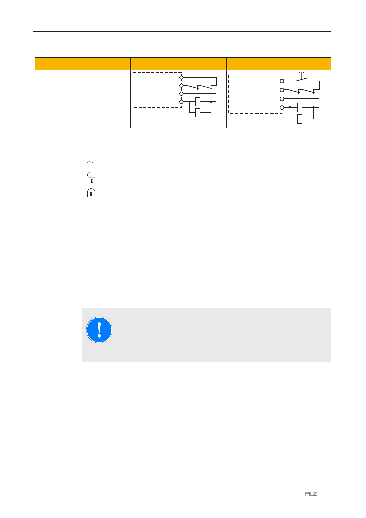
Feedback loop Automatic start Manual start
Contacts from external contactors
K5
K6
K5
L1
N
K6
S12
13 (23,33)
S34
14 (24,34)
K5
K6
K5
L1
K6
S12
S34
S3
N
13 (23, 33)
14 (24 ,34)
Legend
} S1/S2: E-STOP/safety gate switch
} S3: Reset button
} : Switch operated
} : Gate open
} : Gate closed
Operation
When the relay outputs are switched on, the mechanical contact on the relay cannot be
tested automatically. Depending on the operational environment, measures to detect the
non-opening of switching elements may be required under some circumstances.
When the product is used in accordance with the European Machinery Directive, a check
must be carried out to ensure that the safety contacts on the relay outputs open correctly.
Open the safety contacts (switch off output) and start the device again, so that the internal
diagnostics can check that the safety contacts open correctly
} for SIL CL 3/PL e at least 1x per month
} for SIL CL 2/PL d at least 1x per year
NOTICE
The safety function should be checked after initial commissioning and each
time the plant/machine is changed. The safety functions may only be
checked by qualified personnel.
PNOZ X2.8P
Operating Manual PNOZ X2.8P
1004082-EN-21
| 16
Status indicators
LEDs indicate the status and errors during operation:
LED on
POWER
Supply voltage is present.
CH.1
Safety contacts of channel 1 are closed.
CH.2
Safety contacts of channel 2 are closed.
Faults – Interference
} Earth fault: The supply voltage fails and the safety contacts open. Once the cause of the
respective fault has been rectified and the supply voltage is switched off for approx.
1minute, the unit is ready for operation again.
} Contact malfunctions: If the contacts have welded, reactivation will not be possible after
the input circuit has opened.
} LED "POWER" does not light: Short circuit or no supply voltage.
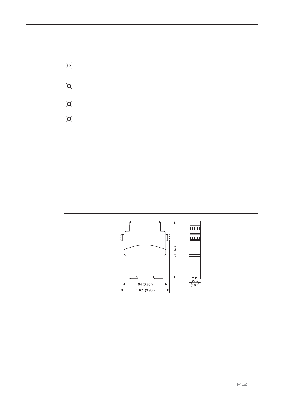
Dimensions in mm
* with spring-loaded terminals
PNOZ X2.8P
Operating Manual PNOZ X2.8P
1004082-EN-21
| 17
Technical details Order no. 777301, 777302
General 777301 777302
Certifications
CCC, CE, EAC, KOSHA, TÜV,
UKCA, cULus Listed
CCC, CE, EAC, KOSHA, TÜV,
UKCA, cULus Listed
Electrical data 777301 777302
Supply voltage
Voltage 24 V 24 - 240 V
Kind AC/DC AC/DC
Voltage tolerance -15 %/+10 % -15 %/+10 %
Output of external power supply
(AC) 5,5 VA 4,5 VA
Output of external power supply
(DC) 2,5 W 2 W
Frequency range AC 50 - 60 Hz 50 - 60 Hz
Residual ripple DC 160 % 160 %
Duty cycle 100 % 100 %
Max. inrush current impulse
Current pulse, A1 1,7 A –
Pulse duration, A1 3,3 ms –
Inputs 777301 777302
Number 2 2
Voltage at
Input circuit DC 24 V 24 V
Start circuit DC 24 V 24 V
Feedback loop DC 24 V 24 V
Current at
Input circuit DC 30 mA 25 mA
Start circuit DC 40 mA 50 mA
Feedback loop DC 40 mA 50 mA
Min. input resistance at power-on 88 Ohm 209 Ohm
Max. overall cable resistance Rl-
max
Single-channel at UB DC 30 Ohm 45 Ohm
Single-channel at UB AC 100 Ohm 45 Ohm
Dual-channel without detection
of shorts across contacts at UB
DC 50 Ohm 80 Ohm
Dual-channel without detection
of shorts across contacts at UB
AC 100 Ohm 80 Ohm
Dual-channel with detection of
shorts across contacts at UB DC 15 Ohm 15 Ohm
Dual-channel with detection of
shorts across contacts at UB AC 15 Ohm 15 Ohm