PNOZ_X2_8P_Operat_Manual_1004082-EN-21.pdf - 第14页
PNOZ X2.8P Operating Manual PNOZ X2.8P 1004082-EN-21 | 14 NOTICE With single-channel wiring the safety level of your machine/plant may be lower than the safety level of the unit (see Safety characteristic data [ 27] ). N…
PNOZ X2.8P
Operating Manual PNOZ X2.8P
1004082-EN-21
| 13
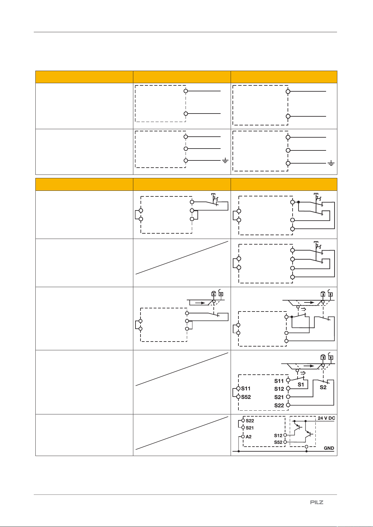
Preparing for operation
Supply voltage AC DC
U
B
= 24 VAC/DC;
Order no. 777301, 787301
A1
A2
L1
N
A1
A2
L+
L-
U
B
= 24 - 240 VAC/DC;
Order no. 777302, 787302
A1
A2
L1
N
S21
A1
A2
L+
L-
S21
Input circuit Single-channel Dual-channel
E-STOP
without detection of shorts
across contacts
S1
S22
S21
S11
S52
S12
S1
S11
S12
S52
S22
S21
E-STOP
with detection of shorts across
contacts
S1
S22
S21
S12
S11
S52
S11
Safety gate
without detection of shorts
across contacts
S1
S22
S21
S11
S52
S12
S1
S2
S22
S21
S11
S12
S52
Safety gate
with detection of shorts across
contacts
Light guards or safety switch, de-
tection of shorts across contacts
via ESPE
(only when U
B
= 24 VDC);
Order no. 777301, 787301)
PNOZ X2.8P
Operating Manual PNOZ X2.8P
1004082-EN-21
| 14
NOTICE
With single-channel wiring the safety level of your machine/plant may be
lower than the safety level of the unit (see Safety characteristic
data [ 27]).
NOTICE
Operation with a light guard or safety switch
It must not be possible to switch off the supply voltage for the PNOZ X2.8P
separately from the supply voltage for the light guard or safety switch.
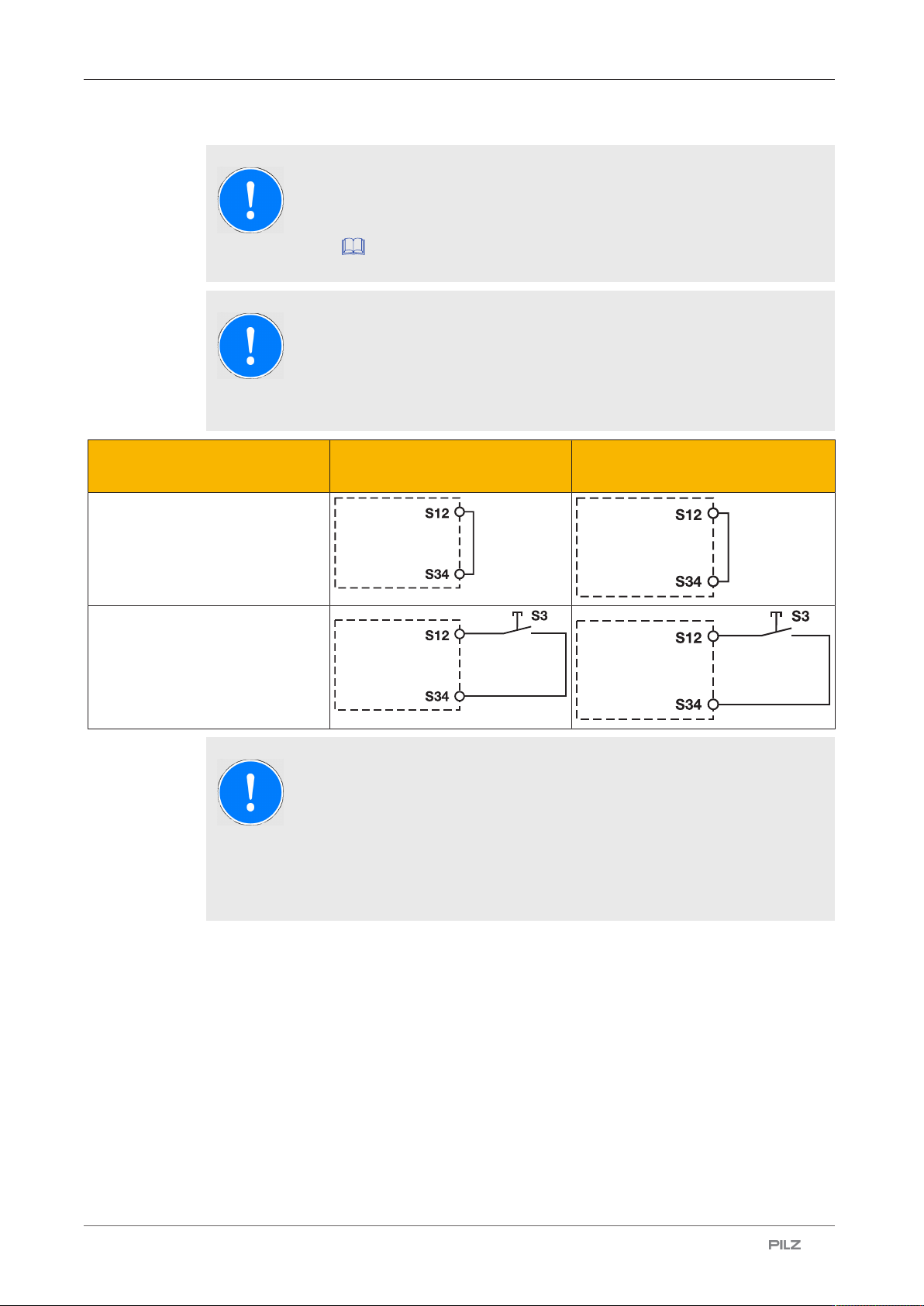
Start circuit E-STOP wiring, safety gate
(single-channel)
E-STOP wiring, safety gate (dual-
channel)
Automatic start
Manual start
NOTICE
In the event of an automatic start or manual start with bridged start
contact (fault):
The unit starts up automatically when the safeguard is reset, e.g. when the
E-STOP pushbutton is released. Use external circuit measures to prevent
an unexpected restart.
PNOZ X2.8P
Operating Manual PNOZ X2.8P
1004082-EN-21
| 15
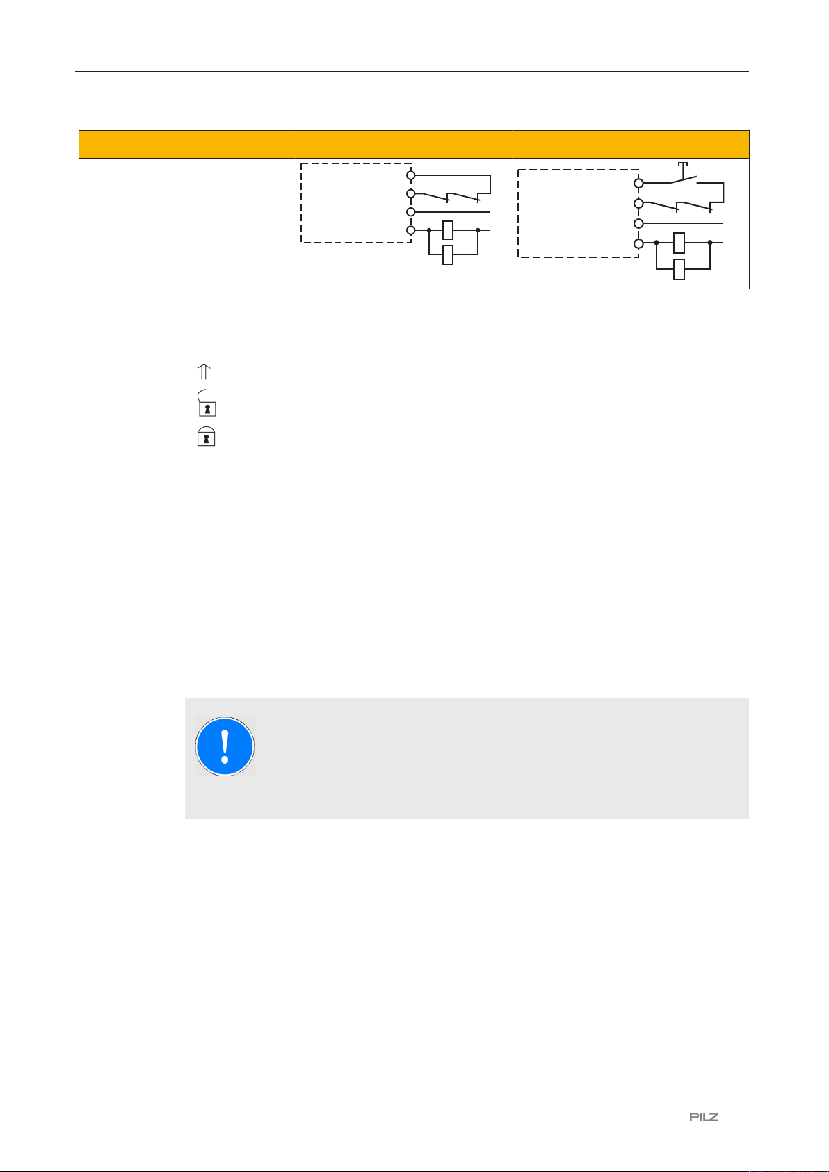
Feedback loop Automatic start Manual start
Contacts from external contactors
K5
K6
K5
L1
N
K6
S12
13 (23,33)
S34
14 (24,34)
K5
K6
K5
L1
K6
S12
S34
S3
N
13 (23, 33)
14 (24 ,34)
Legend
} S1/S2: E-STOP/safety gate switch
} S3: Reset button
} : Switch operated
} : Gate open
} : Gate closed
Operation
When the relay outputs are switched on, the mechanical contact on the relay cannot be
tested automatically. Depending on the operational environment, measures to detect the
non-opening of switching elements may be required under some circumstances.
When the product is used in accordance with the European Machinery Directive, a check
must be carried out to ensure that the safety contacts on the relay outputs open correctly.
Open the safety contacts (switch off output) and start the device again, so that the internal
diagnostics can check that the safety contacts open correctly
} for SIL CL 3/PL e at least 1x per month
} for SIL CL 2/PL d at least 1x per year
NOTICE
The safety function should be checked after initial commissioning and each
time the plant/machine is changed. The safety functions may only be
checked by qualified personnel.