PNOZ_X2_8P_Operat_Manual_1004082-EN-21.pdf - 第28页
PNOZ X2.8P Operating Manual PNOZ X2.8P 1004082-EN-21 | 28 Supplementary data CAUTION! It is essential to consider the relay's service life graphs. The relay outputs' safety-related characteristic data is only v…
PNOZ X2.8P
Operating Manual PNOZ X2.8P
1004082-EN-21
| 27
Safety characteristic data
NOTICE
You must comply with the safety characteristic data in order to achieve the
required safety level for your plant/machine.
Operating
mode
EN ISO
13849-1:
2015
PL
EN ISO
13849-1:
2015
Category
EN62061
SIL CL
EN62061
PFH
D
[1/h]
IEC61511
SIL
IEC61511
PFD
EN ISO
13849-1:
2015
T
M
[year]
– PL e Cat. 4 SIL CL 3 2,31E-09 SIL 3 2,03E-06 20
Explanatory notes for the safety-related characteristic data:
} The SIL CL value in accordance with EN 62061 corresponds to the SIL value in accord-
ance with EN 61508.
} T
M
is the maximum mission time in accordance with EN ISO 13849-1. The value also ap-
plies as the retest interval in accordance with EN 61508-6 and IEC 61511 and as the
proof test interval and mission time in accordance with EN 62061.
All the units used within a safety function must be considered when calculating the safety
characteristic data.
INFORMATION
A safety function's SIL/PL values are not identical to the SIL/PL values of
the units that are used and may be different. We recommend that you use
the PAScal software tool to calculate the safety function's SIL/PL values.
PNOZ X2.8P
Operating Manual PNOZ X2.8P
1004082-EN-21
| 28
Supplementary data
CAUTION!
It is essential to consider the relay's service life graphs. The relay outputs'
safety-related characteristic data is only valid if the values in the service life
graphs are met.
The PFH value depends on the switch frequency and the load of the relay output.
If the service life graphs are not accessible, the stated PFH value can be used irrespective
of the switch frequency and the load, as the PFH value already considers the relay's B10d
value as well as the failure rates of the other components.
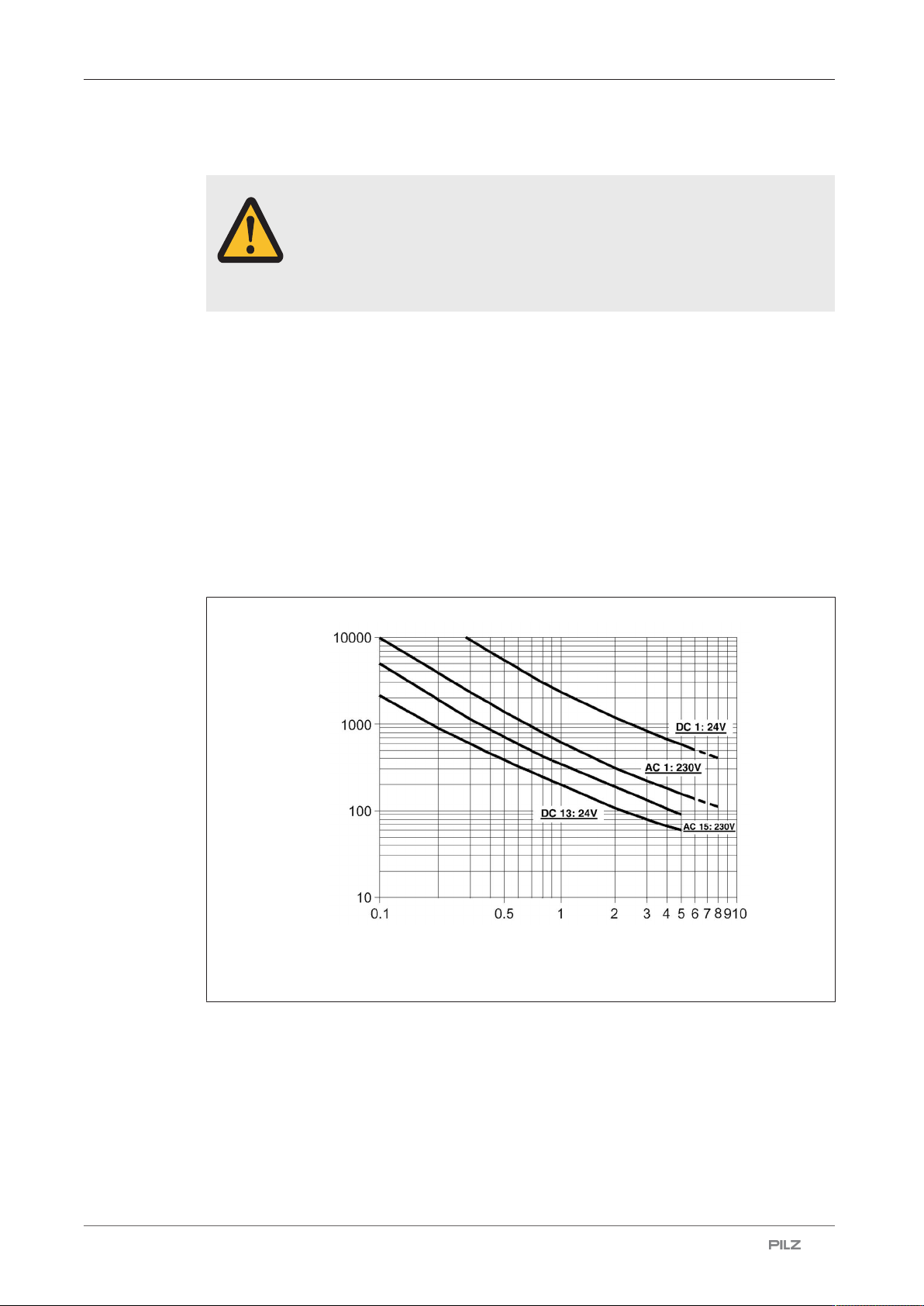
Service life graph
The service life graphs indicate the number of cycles from which failures due to wear must
be expected. The wear is mainly caused by the electrical load; the mechanical load is negli-
gible.
Unit types with UB 24 VAC/DC
} U
B
: 24 VAC/DC; Order no. 777301, 787301
Cycles x 1000
Switching current (A)
Fig.: Service life graphs at 24 V DC and 230 V AC
PNOZ X2.8P
Operating Manual PNOZ X2.8P
1004082-EN-21
| 29
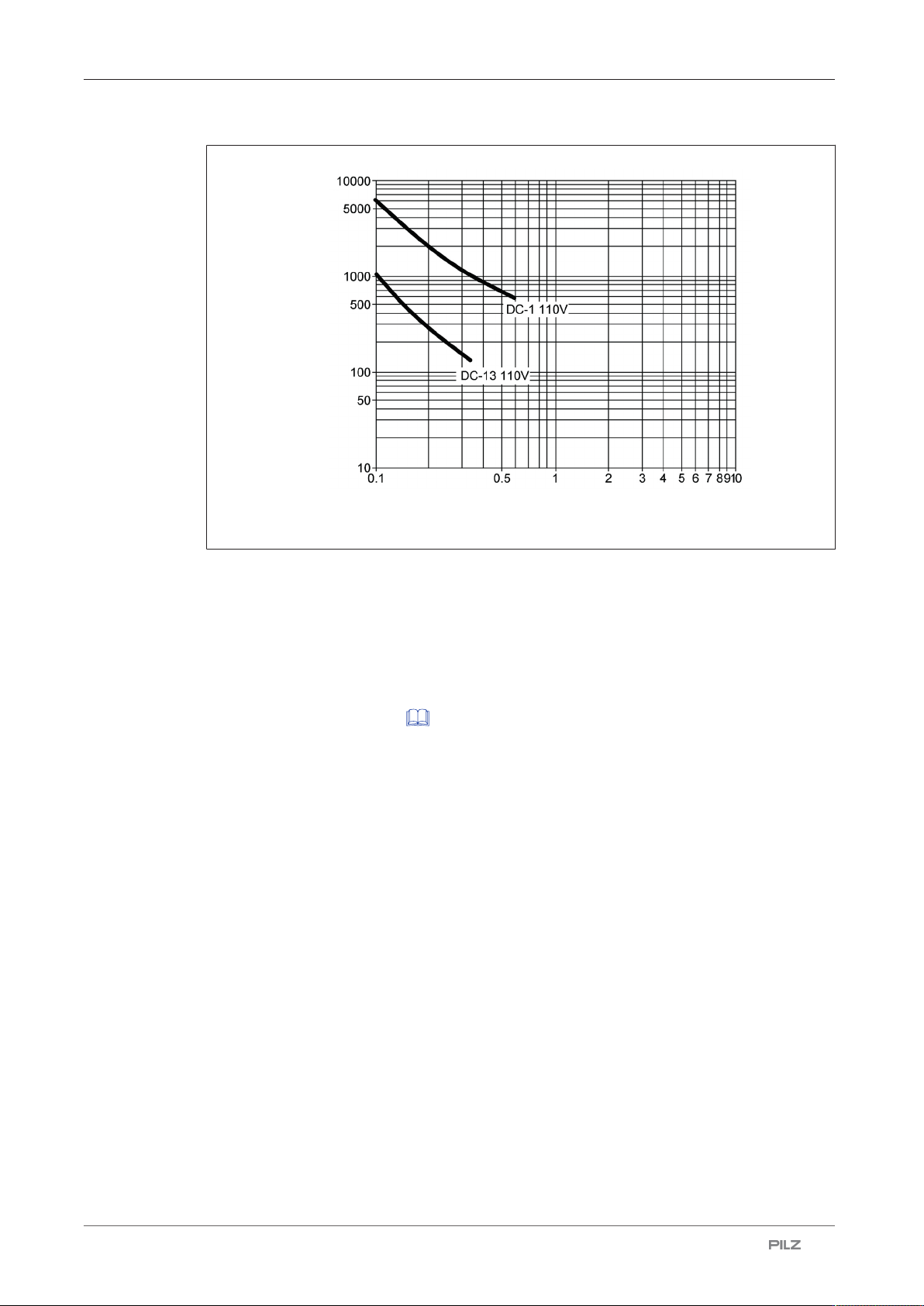
Cycles x 1000
Switching current (A)
Fig.: Service life graphs at 110 V DC
Example
} Inductive load: 0.2 A
} Utilisation category: AC15
} Contact service life: 2 000 000 cycles
Provided the application to be implemented requires fewer than 2 000 000 cycles, the PFH
value (see Technical details [ 17]) can be used in the calculation.
To increase the service life, sufficient spark suppression must be provided on all output
contacts. With capacitive loads, any power surges that occur must be noted. With DC con-
tactors, use flywheel diodes for spark suppression.