PNOZ_X2_8P_Operat_Manual_1004082-EN-21.pdf - 第12页
PNOZ X2.8P Operating Manual PNOZ X2.8P 1004082-EN-21 | 12 Wiring Please note: } Information given in the " Technical details [ 17] " must be followed. } Outputs 13-14, 23-24, 33-34 are safety contacts; output 4…
PNOZ X2.8P
Operating Manual PNOZ X2.8P
1004082-EN-21
| 11
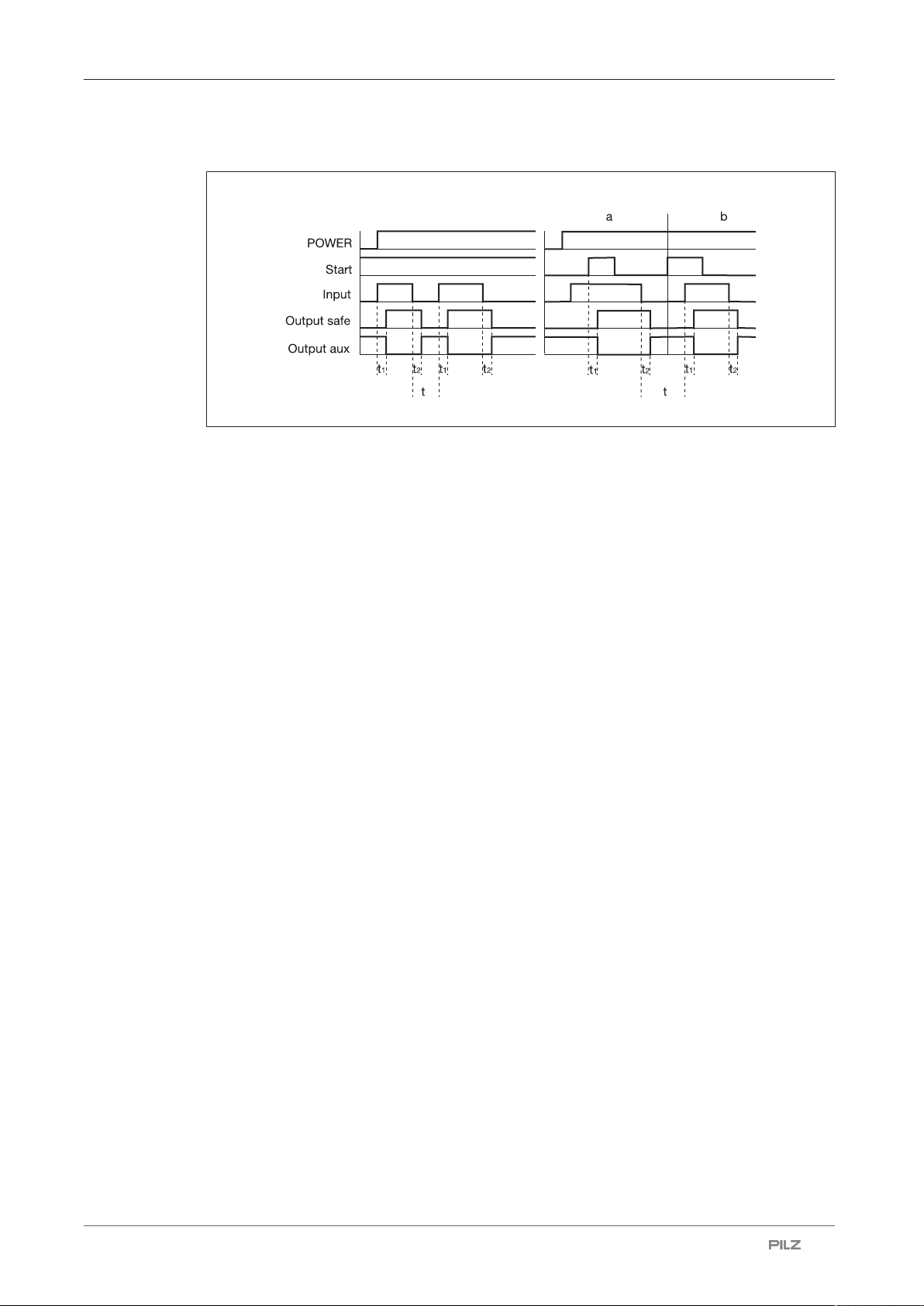
Timing diagram
[1][1] [2][2]
3 3
Legend
} Power: Supply voltage
} Start: Start circuit
} Input: Input circuit
} Output safe: Safety contacts
} Output aux: Auxiliary contact
} [1]: Automatic start
} [2]: Manual start
} a: Input circuit closes before start circuit
} b: Start circuit closes before input circuit
} t
1
: Switch-on delay
} t
2
: Delay-on de-energisation
} t
3
: Recovery time
Installation
} The unit should be installed in a control cabinet with a protection type of at least IP54.
} Use the notch on the rear of the unit to attach it to a DIN rail (35 mm).
} When installed vertically: Secure the unit by using a fixing element (e.g. retaining bracket
or end angle).

PNOZ X2.8P
Operating Manual PNOZ X2.8P
1004082-EN-21
| 12
Wiring
Please note:
} Information given in the "Technical details [ 17]" must be followed.
} Outputs 13-14, 23-24, 33-34 are safety contacts; output 41-42 is an auxiliary contact (e.g.
for display).
} Auxiliary contact 41-42 shouldnot be used for safety circuits!
} To prevent contact welding, a fuse should be connected before the output contacts (see
Technical details [ 17]).
} Calculation of the max. cable length l
max
in the input circuit:
R
lmax
R
l
/ km
I
max
=
R
lmax
= max. overall cable resistance (see Technical details [ 17])
R
l
/km = cable resistance/km
} Use copper wiring with a temperature stability of 60/75 °C.
} To prevent EMC interferences (particularly common-mode interferences) the measures
described in EN60204-1 must be executed. This includes the separate routing of cables
of the control circuits (input, start and feedback loop) from other cables for energy trans-
mission or the shielding of cables, for example.
} Adequate protection must be provided on all output contacts with capacitive and inductive
loads.
} Do not switch low currents using contacts that have been used previously with high cur-
rents.
} When connecting magnetically operated, reed proximity switches, ensure that the max.
peak inrush current (on the input circuit) does not overload the proximity switch.
} With 24 V AC/DC units:
The power supply must meet the regulations for extra low voltages with protective elec-
trical separation (SELV, PELV).
Important for detection of shorts across contacts:
As this function for detecting shorts across contacts is not failsafe, it is tested by Pilz during
the final control check. If there is a danger of exceeding the cable runs, we recommend the
following test after the installation of the device:
1. Unit ready for operation (output contacts closed)
2. Short circuit the test terminals S12, S22 for detecting shorts across the inputs.
3. The unit's fuse must be triggered and the output contacts must open. Cable lengths in
the scale of the maximum length can delay the fuse triggering for up to 2 minutes.
4. Reset the fuse: remove the short circuit and switch off the supply voltage for approx. 1
minute.
PNOZ X2.8P
Operating Manual PNOZ X2.8P
1004082-EN-21
| 13
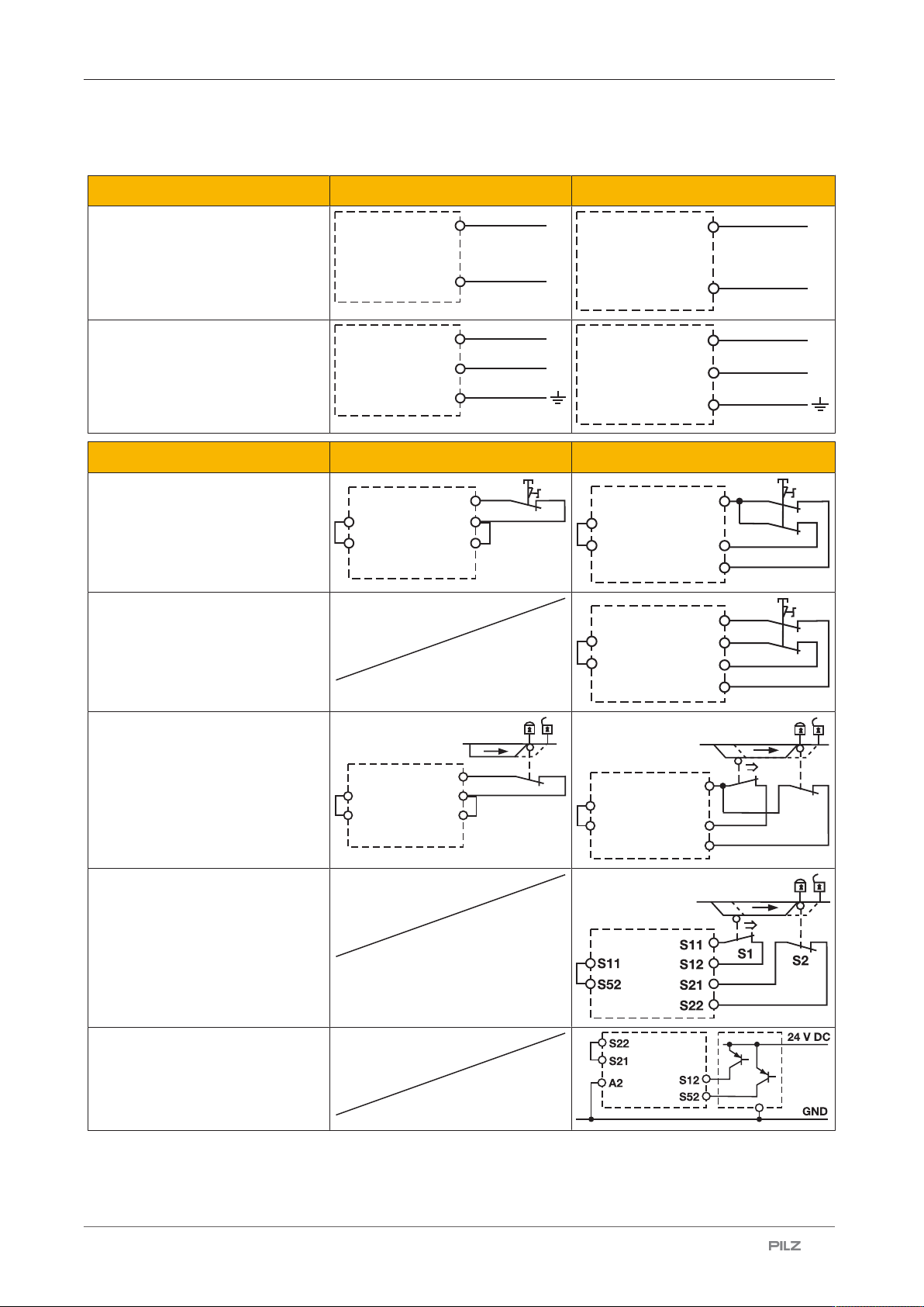
Preparing for operation
Supply voltage AC DC
U
B
= 24 VAC/DC;
Order no. 777301, 787301
A1
A2
L1
N
A1
A2
L+
L-
U
B
= 24 - 240 VAC/DC;
Order no. 777302, 787302
A1
A2
L1
N
S21
A1
A2
L+
L-
S21
Input circuit Single-channel Dual-channel
E-STOP
without detection of shorts
across contacts
S1
S22
S21
S11
S52
S12
S1
S11
S12
S52
S22
S21
E-STOP
with detection of shorts across
contacts
S1
S22
S21
S12
S11
S52
S11
Safety gate
without detection of shorts
across contacts
S1
S22
S21
S11
S52
S12
S1
S2
S22
S21
S11
S12
S52
Safety gate
with detection of shorts across
contacts
Light guards or safety switch, de-
tection of shorts across contacts
via ESPE
(only when U
B
= 24 VDC);
Order no. 777301, 787301)