00194335-02.pdf - 第27页
Coplanarity module 2 Retrofit instructions Coplanarity module - SIPLACE HF series 10/2004 Edition 27 : Plug the ca ble to the c oplanar ity module in at th e RS 485 in terface on th e front panel of the computer unit. 2 …
2 Retrofit instructions Coplanarity module - SIPLACE HF series Coplanarity module
10/2004 Edition
26
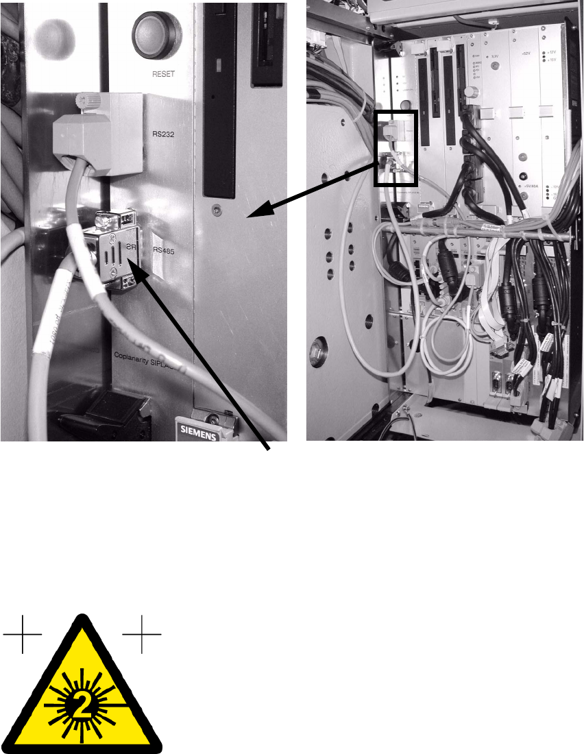
: Guide the cable along the thick cable bundle to the computer unit.
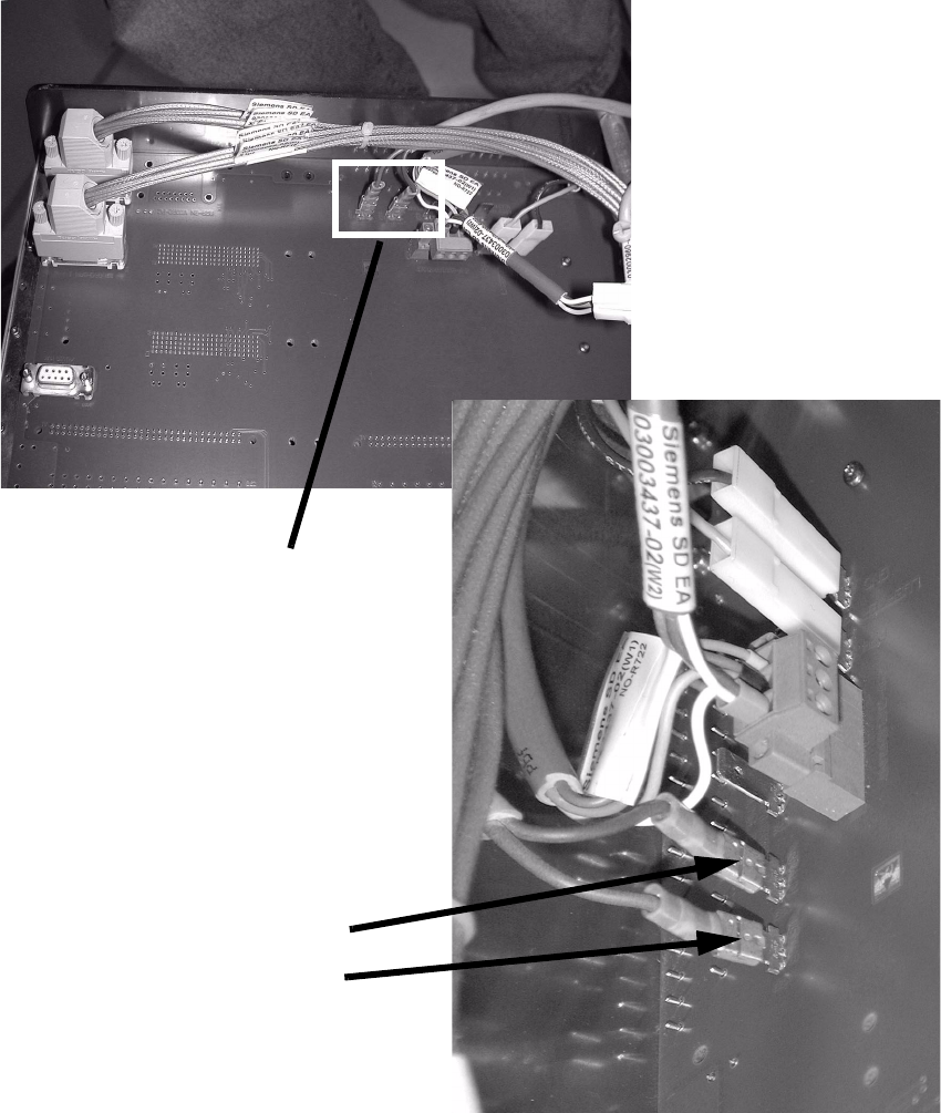
: Plug in the two lines on the back panel of the computer unit.
2
2
2
2
Connector (white)
Connector (black)
2 connectors
Coplanarity module 2 Retrofit instructions Coplanarity module - SIPLACE HF series
10/2004 Edition
27
: Plug the cable to the coplanarity module in at the RS 485 interface on the front panel of the
computer unit.
2
: Push all the units back into position and refit all the covers.
: Connect the RS232 interface of the coplanarity module and the COM-A interface of the ma-
chine controller using the interface cable (00336796-02).
: Stick the warning label visible onto the coplanarity module.
2
: Switch the placement machine on at the main switch.
Cable to coplanarity module
2 Retrofit instructions Coplanarity module - SIPLACE HF series Coplanarity module
10/2004 Edition
28
2.2 Activate coplanarity in the SITEST program
: Start the SITEST program.
: In the main view, select
"Options --> Operator level --> Service engineer --> Activate".
: Select
"Options --> Machine configuration --> (relevant) Handling area".
: Activate
"ILD 2000 (type 17)" and "Accept".
2
: Shut down the station computer and switch off the placement machine at the main switch.
2.3 Check the safety shutdown
The safety measurement checks whether the voltage (24 V) is switched off when the safety circuit
is broken (e.g. protective covers opened or emergency stop pressed). 2
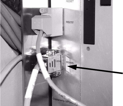
: Unplug the coplanarity sensor cable from the RS485 slot (see photograph).
: Plug in the coplanarity test plug at this slot.
2
2
RS 485