5-p0921-0943-vba_en.pdf - 第10页
Design W arn ing 1. Warning concerning abnormal outlet pressure • If there is a likelihood of causing an outlet pressure drop due to un for ese en circ ums tan ces su ch as equ ipm ent malfunction, thus leading to a majo…
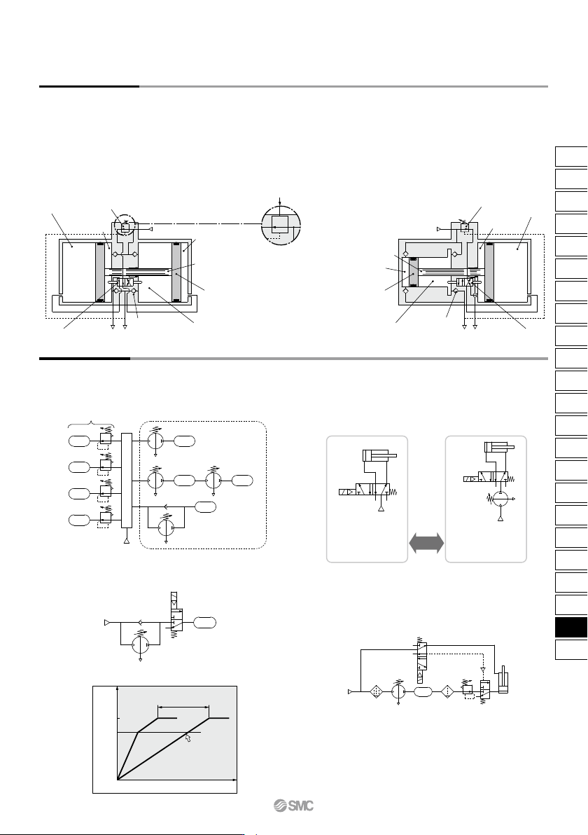
VBA22A, 42A
Air-operated type
Pilot pressure
IN (Inlet)
Governor
Booster
chamber A
Drive
chamber A
Switching valve
Piston
Drive chamber B
Booster chamber B
Check valve
OUT (Outlet)E
Piston rod
General line (low pressure) Locations requiring high pressure
Shortening time
Without check
valve by-pass
Time t (S)
Outlet pressure (MPa)
P2
P1
0
Operating pressure:
0.5 MPa
Bore size: ø100
Output ≈ 3850 N
Operating pressure:
0.8 MPa
Bore size: ø80
Output ≈ 4000 N
Equivalent
output
0.5 MPa
ø100
IN 0.5 MPa
E
ø80
OUT 0.8 MPa
P2
P1
VBA
VBA
VBA
Circuit Example
Working Principle
The IN air passes through the check valve to booster chambers A and B. Meanwhile, air is supplied to drive chamber B via the governor and
the switching valve. Then, the air pressure from drive chamber B and booster chamber A are applied to the piston, boosting the air in booster
chamber B. As the piston travels, the boosted air is pushed via the check valve to the OUT side. When the piston reaches to the end, the piston
causes the switching valve to switch, so that drive chamber B is in the exhaust state and drive chamber A is in the supply state respectively.
Then, the piston reverses its movement, this time, the pressures from booster chamber B and drive chamber A boosts the air in booster
chamber A and sends it to the OUT side. The process described above is repeated to continuously supply highly pressurized air from the IN to
the OUT side. The governor establishes the outlet pressure by handle operation and pressure adjustment in the drive chamber by feeding back
the outlet pressure.
VBA10A, 20A, 40A, 43A
Initially, inlet pressure (P1) passes through the check valve, fills P2,
and results in P1 = P2.
• When only some of the machines in the plant require high-pressure
air, booster regulators can be installed for only the equipment that
requires it. This allows the overall system to use low-pressure air
while accommodating machines requiring high-pressure air.
• When the actuator output is insufficient but space limitations prohibit
switching to a larger cylinder diameter, a booster regulator can be
used to increase the pressure. This makes it possible to boost the
output without replacing the actuator.
• When a certain level of output is required but the cylinder size must
be kept small so that the driver remains compact.
• When charging a tank or the like from a source at atmospheric
pressure, a circuit with a check valve can be used to reduce the
charge time by allowing air to pass through the check valve up to
the inlet pressure.
• When only one side of the cylinder is used for work, booster
regulators can be installed only on the lines that require them to
reduce the overall air consumption volume.
Booster Regulator Series VBA
(Two-stage
pressure boost)
VBA
Plant line (source pressure)
Piston rod
EOUT (Outlet)
Check valve
Booster
chamber B
Drive
chamber B
Piston
Switching valve
Drive
chamber A
Booster
chamber A
Governor
IN (Inlet)
VBA11A
929
ARJ
AR425
to 935
ARX
AMR
ARM
ARP
IR
IRV
VEX
SRH
SRP
SRF
VCHR
ITV
IC
ITVX
PVQ
VEF
VEP
VER
VEA
VY1
VBA
VBAT
AP100
VBA
VBAT
A
Design
Warning
1. Warning concerning abnormal outlet pressure
• If there is a likelihood of causing an outlet pressure drop
due to unforeseen circumstances such as equipment
malfunction, thus leading to a major problem, take safety
measures on the system side.
• Because the outlet pressure could exceed its set range if
there is a large fluctuation in the inlet pressure, leading to
unexpected accidents, take safety measures against abnor-
mal pressures.
• Operate the equipment within its maximum operating
pressure and set pressure range.
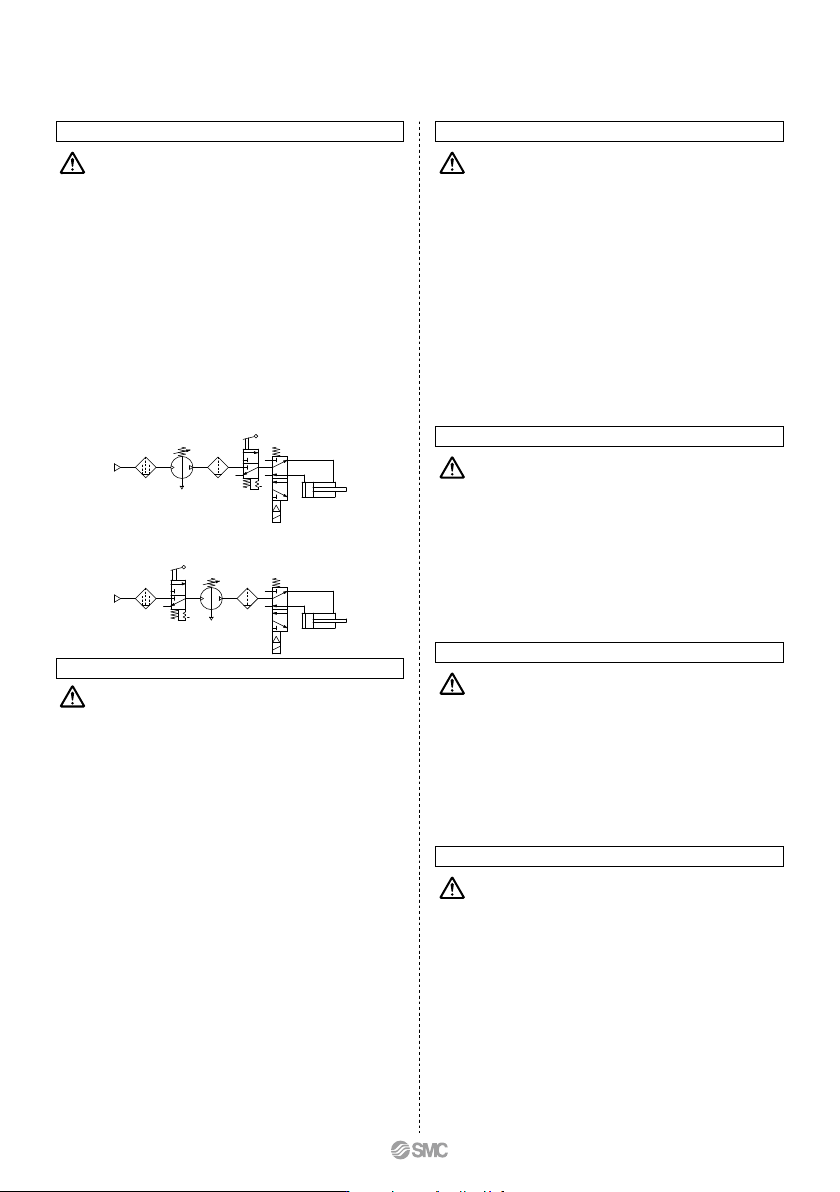
2. Residual pressure measures
• Connect a 3-port valve to the OUT side of the booster
regulator if the residual pressure must be released quickly
from the outlet pressure side for maintenance, etc. (Refer to
the diagram below.) The residual outlet pressure side
cannot be released even if the 3-port valve is connected to
the IN side because the check valve in the booster regulator
will activate.
• After operation is finished, release the supply pressure at
the inlet. This stops the booster regulator from moving
needlessly and prevents operating malfunctions.
Selection
Caution
1. Check the specifications.
• Consider the operating conditions and operate this product
within the specification range that is described in this
catalog.
2. Selection
• Based on the conditions (such as pressure, flow rate, takt
time) required for the outlet side of the booster regulator,
select the size of the booster regulator in accordance with
the selection procedures described in this catalog or model
selection program.
• Use the VBA11A (pressure increase ratio 4) with pressure
increase ratio 2 to 4. Usage of pressure increase ratio
below 2 is preferred for the VBA10A (pressure increase
ratio 2). A stable operation and increased life expectancy
will result.
• Inlet supply pressure volume is {approximately twice
(pressure increase ratio 2), approx. 4 times (pressure
increase ratio 4)} the volume of the outlet side. Booster
regulator requires the inlet side volume which is the sum of
the flow volume running into the outlet side and the volume
exhausted from E port (for driving), because air is the power
source.
• When running continuously for longer periods of time,
confirm the life expectancy. The life expectancy of a booster
regulator is dependent upon the operational cycle. Thus,
when used for driving cylinders, etc. in the outlet side, life
expectancy will be reduced.
• Make sure the outlet pressure is set 0.1 MPa or higher than
the inlet pressure. A pressure difference below 0.1 MPa
makes the operation unstable and may result in a malfunc-
tion.
Mounting
Caution
1. Transporting
• When transporting this product, hold it lengthwise with both
hands. Never hold it by the black handle that protrudes from
the center because the handle could become detached
from the body, causing the body to fall and leading to injury.
2. Installation
• Install this product so that the silver-colored tie-rods and
cover are placed horizontally. If mounted vertically, it may
result in a malfunction.
• Because the piston cycle vibration is transferred, use the
following mounting bolts (VBA1: M5; VBA2, 4: M10) and
tighten them with the specified torque (VBA1: 3 N·m; VBA2,
4: 24 N·m).
• If the transmission of vibration is not preferred, insert an
isolating rubber material before installation.
• Mount the pressure gauge with a torque of 7 to 9 N·m.
Piping
Caution
1. Flushing
• Use an air blower to flush the piping to thoroughly remove
any cutting chips, cutting oil, or debris from the piping
inside, before connecting them. If they enter the inside of
the booster regulator, they could cause the booster regula-
tor to malfunction or its durability could be affected.
2. Piping size
• To bring the booster regulator’s ability into full play, make
sure to match the piping size to the port size.
Air Supply
Caution
1. Quality of air source
• Connect a mist separator to the inlet side near the booster
regulator. If the quality of the compressed air is not
thoroughly controlled, the booster regulator could malfunc-
tion (without being able to boost) or its durability could be
affected.
• If dry air (atmospheric pressure dew point: –23°C or less) is
used, the life expectancy may be shortened because dry air
will accelerate evaporation of grease inside.
Operating Environment
Caution
1. Installation location
• Do not install this product in an area that is exposed to
rainwater or direct sunlight.
• Do not install in locations influenced by vibrations. If it must
be used in such an area due to unavoidable circumstances,
please contact SMC beforehand.
Series VBA
930
Handling
1
0.9
0.8
0.7
0.6
0.5
0.5
0.4
0.4
0.3
0.3
0.2
0.2
Pilot pressure MPa
0.1
0.1
0
Outlet pressure MPa (Q = 0)
SMC
HighLow
1. Setting the pressure on the handle-operated type
• If air is supplied to the product in the shipped state, the air
will be released.
Set the pressure by quickly pulling up on the governor
handle, releasing the lock, and rotating the handle in the
direction of the arrow (+).
• There is an upper and lower limit for the handle rotation. If
over-rotating the handle even after reaching to the limit, the
internal parts may be damaged. If the handle suddenly feels
heavy while being turned, stop turning the handle.
• Once the setting is completed, push the handle down and
lock it.
• To decrease the outlet pressure, after the pressure has
been set, rotate the handle in the direction of the arrow (–).
The residual air will be released from the area of the
handle, due to the relief construction of the governor.
• To reset the pressure, first reduce the pressure so that it is
lower than the desired pressure; then, set it to the desired
pressure.
Caution
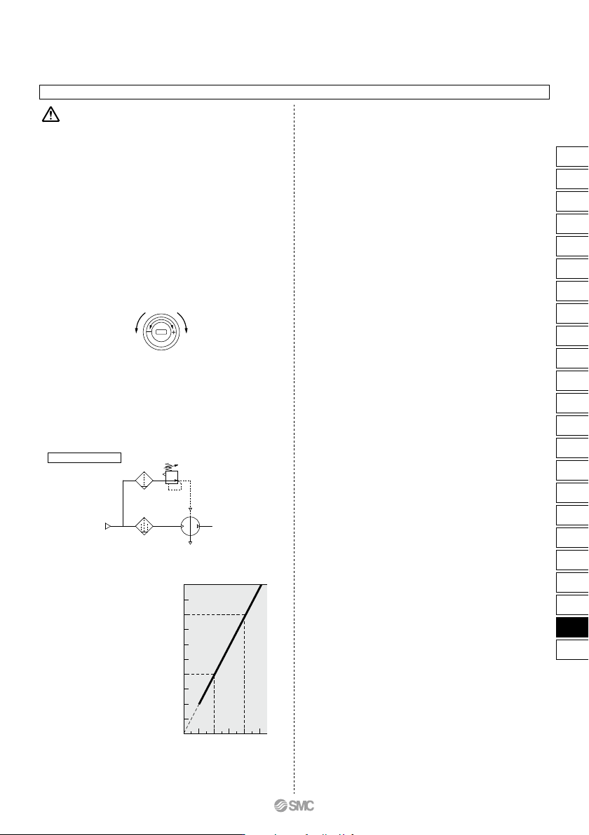
2. Setting the pressure on the air-operated type
(VBA22A, 42A)
• Connect the outlet pipe of the pilot regulator for the remote
control to the pilot port (P). (Refer to the diagram below.)
• Refer to the graph below for the relationship between the
pilot pressure and outlet pressure.
• The AR20 and AW20 are recommended for the pilot regula-
tor.
Pilot regulator
• The outlet pressure is twice the pilot pressure.
• When the inlet pressure is 0.4 MPa:
Pilot pressure
0.2 MPa to 0.4 MPa
Outlet pressure
0.4 MPa to 0.8 MPa
3. Draining
• If this product is used with a large amount of drainage
accumulated in the filter, mist separator or tank, the
drainage could flow out, leading to equipment malfunction.
Therefore, drain the system once a day. If it is equipped
with an auto drain, check its operation once a day.
4. Exhaust
• Exhausting time from E port may be longer for a booster
regulator which is set to switch in longer hour intervals. This
is not an abnormal phenomenon.
5. Maintenance
• Life expectancy varies depending on the quality of air and
the operating conditions. Signs that the unit is reaching the
end of its service life include the following:
•
Constant bleed from under the handle.
•
Air exhaust noise can be heard from the booster regulator
at 10 to 20 second intervals even when there is no air
consumption on the outlet side.
Conduct maintenance earlier than scheduled in such cases.
• When maintenance is required, confirm the model and serial
number of the booster regulator, and please contact SMC
for maintenance kit.
• Conduct maintenance according to the specified mainte-
nance procedure by individuals possessing enough knowl-
edge and experiences in maintaining pneumatic equipment.
• The list of replacement parts and kit number are shown on
page 932, and the figure shows the position of the parts.
Booster Regulator Series VBA
P
E
IN
OUT
931
ARJ
AR425
to 935
ARX
AMR
ARM
ARP
IR
IRV
VEX
SRH
SRP
SRF
VCHR
ITV
IC
ITVX
PVQ
VEF
VEP
VER
VEA
VY1
VBA
VBAT
AP100
VBA
VBAT