5-p0921-0943-vba_en.pdf - 第6页
12 11 10 9 8 7 6 5 4 3 2 1 0 Charge time per 10 L t (s) 1.0 1.1 1.2 1.3 1.4 1.5 1.6 1.7 1.8 1.9 2.0 Pressure increase ratio P 2 /P 1 1.0 0.8 0.6 0.4 0.2 Outlet pressure (MPa) 0 200 400 600 800 1000 1200 Outlet air flow r…
1. System configuration
• The IN port of the booster regulator has metallic mesh to prevent
dust from entering the booster regulator. However, it cannot
remove dust continuously or separate drainage. Make sure to
install a mist separator (AM series) on the inlet side of the
booster regulator.
• The booster regulator has a sliding part inside, and it generates
dust. Also, install an air purification device such as an air filter or
a mist separator on the outlet side as necessary.
• Connect a lubricator to the outlet side, because the accumulated
oil in the booster regulator may result in a malfunction.
2. Exhaust air measures
• Provide a dedicated pipe to release the exhaust air from each
booster regulator. If exhaust air is converged into a pipe, the
back pressure that is created could cause improper operation.
• Depending on the necessity, install a silencer or an exhaust
cleaner on the exhaust port of the booster regulator to reduce
the exhaust noise.
3. Maintenance space
• Allow the sufficient space for maintenance and inspection.
Caution
Design
Related Products/Part No.
Options/Part No.
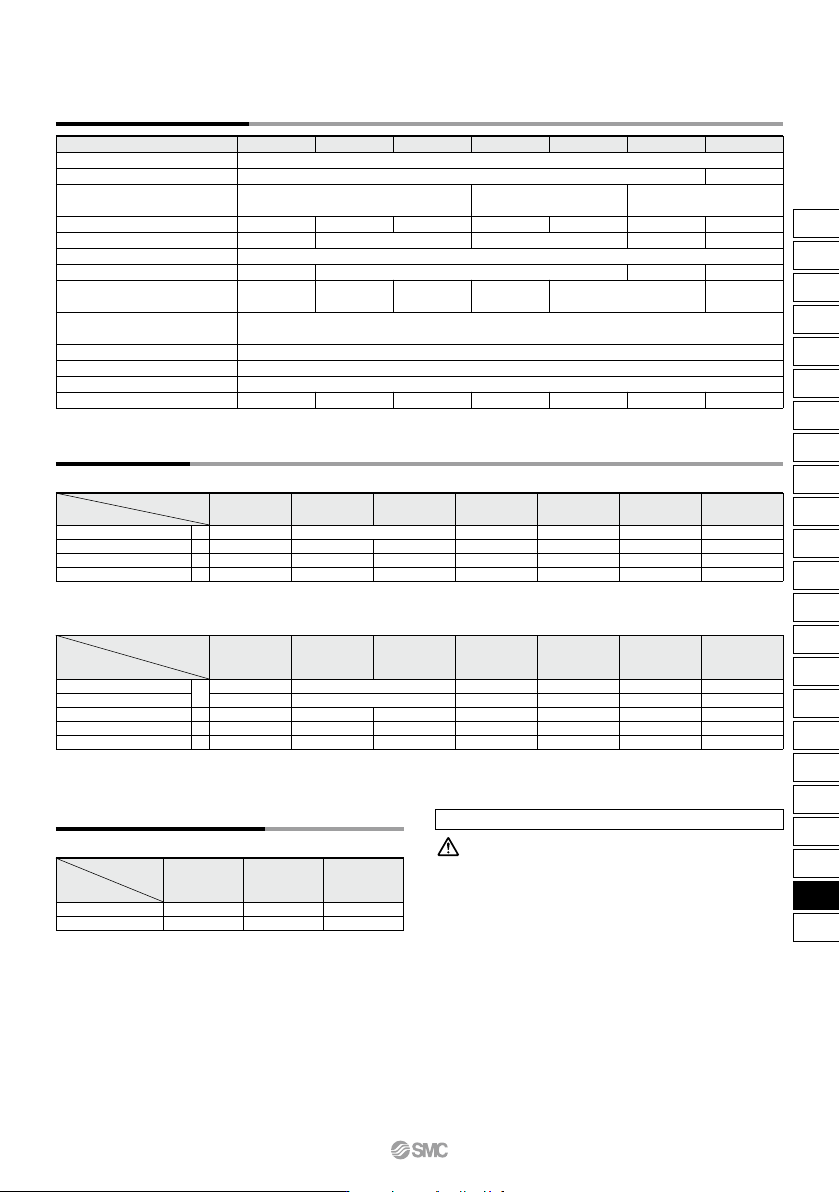
Standard Specifications
Note) Refer to page 935 for air tanks, page 201 for mist separators and Best
Pneumatics No.6 for exhaust cleaners.
Refer to the separate operation manual for the connection method.
Description
Model
Mist separator
Exhaust cleaner
For VBA10A-02
For VBA11A-02
For VBA20A-03
For VBA22A-03
AM250C-02
AMC310-03
AM450C-04, 06
AMC510-06
AM550C-06, 10
AMC610-10
For VBA40A-04
For VBA42A-04
For VBA43A-04
Note 1) If the OUT pressure is higher than the set pressure by the handle, excess pressure is exhausted from the back of the handle.
Note 2) Flow rate at IN= OUT= 0.5 MPa. The pressure varies depending on the operating conditions. Refer to “Flow-rate Characteristics” on pages 926 and 927.
Model
Fluid
Pressure increase ratio
Pressure adjustment mechanism
Max. flow rate
Note 2)
(L/min (ANR))
Set pressure range (MPa)
Supply pressure range (MPa)
Proof pressure (MPa)
Ambient and fluid temperature (°C)
Installation
Lubrication
Weight (kg)
Port size (Rc)
(IN/OUT/EXH: 3 locations)
Pressure gauge port size (Rc)
(IN/OUT: 2 locations)
VBA10A-02 VBA20A-03 VBA40A-04 VBA22A-03 VBA42A-04 VBA11A-02VBA43A-04
Compressed air
0.1 to 1.0
2 to 50 (No freezing)
Horizontal
Grease (Non-lube)
Twice
230
0.2 to 2.0
3
1/4
0.84
1000
0.2 to 1.0
1.5
0.2 to 1.0
1900 1000 1900 70
0.2 to 2.0
1600
0.2 to 1.6
2 to 4 times
Handle-operated with
relief mechanism
Note 1)
Handle-operated with relief mechanism
Note 1)
Air-operated
3/8
3.9
1/2
1/8
3/8 1/2
8.6
3.9 8.6
3
1/4
0.89
2.4
8.6
Note 1) In the case of options GN, two pressure gauges and one silencer are included in the same container as accessories.
Note 2) KT-VBA22A-7 is a pressure gauge with fitting. (Please order two units when using with IN and OUT.)
Pressure Gauge, Silencer (When thread type is Rc or G.)
Model
Description
Pressure gauge
Silencer
High-noise reduction silencer
Elbow for silencer
G
N
S
L
VBA43A-04
VBA43A-F04
VBA42A-04
VBA42A-F04
VBA22A-03
VBA22A-F03
VBA40A-04
VBA40A-F04
VBA20A-03
VBA20A-F03
VBA10A-02
VBA10A-F02
VBA11A-02
VBA11A-F02
G27-20-01
AN20-02
ANA1-02
KT-VBA10A-18
G27-20-01
AN20-02
ANA1-02
KT-VBA10A-18
G36-10-01
AN30-03
ANA1-03
—
AN40-04
ANA1-04
—
KT-VBA22A-7
AN30-03
ANA1-03
—
G36-10-01
AN40-04
ANA1-04
—
G27-20-01
AN40-04
ANA1-04
—
Note 1) In the case of options GN, two pressure gauges and one silencer are included in the same container as accessories.
Note 2) KT-VBA22A-7N, KT-VBA22A-8N are pressure gauges with fittings. (Please order two units when using with IN and OUT.)
Note 3) Under the new measurement law, the pressure unit of “psi” on the pressure gauges cannot be used in Japan.
Note 4) Pressure unit on the pressure gauge: psi
Pressure Gauge, Silencer (When thread type is NPT or NPTF.)
Model
Description
G
N
S
L
VBA10A-N02
∗
VBA10A-T02
∗
∗
: when “-Z”
VBA11A-N02
∗
VBA11A-T02
∗
∗
: when “-Z”
VBA20A-N03
∗
VBA20A-T03
∗
∗
: when “-Z”
VBA40A-N04
∗
VBA40A-T04
∗
∗
: when “-Z”
VBA22A-N03
∗
VBA22A-T03
∗
∗
: when “-Z”
VBA42A-N04
∗
VBA42A-T04
∗
∗
: when “-Z”
VBA43A-N04
∗
VBA43A-T04
∗
∗
: when “-Z”
G27-20-01
G27-P20-01
AN20-N02
—
KT-VBA10A-18N
G27-20-01
G27-P20-01
AN20-N02
—
KT-VBA10A-18N
G36-10-N01
G36-P10-N01
AN30-N03
ANA1-N03
—
AN40-N04
ANA1-N04
—
KT-VBA22A-7N
KT-VBA22A-8N
AN30-N03
ANA1-N03
—
G36-10-N01
G36-P10-N01
AN40-N04
ANA1-N04
—
G27-20-N01
G27-P20-N01
AN40-N04
ANA1-N04
—
Mist Separator, Exhaust Cleaner
Pressure gauge
∗: when Nil
Pressure gauge ∗: when “-Z”
Note 4)
Silencer
High-noise reduction silencer
Elbow for silencer
Booster Regulator Series VBA
925
ARJ
AR425
to 935
ARX
AMR
ARM
ARP
IR
IRV
VEX
SRH
SRP
SRF
VCHR
ITV
IC
ITVX
PVQ
VEF
VEP
VER
VEA
VY1
VBA
VBAT
AP100
VBA
VBAT
12
11
10
9
8
7
6
5
4
3
2
1
0
Charge time per 10 L t (s)
1.0 1.1 1.2 1.3 1.4 1.5 1.6 1.7 1.8 1.9 2.0
Pressure increase ratio P2/P1
1.0
0.8
0.6
0.4
0.2
Outlet pressure (MPa)
0 200 400 600 800 1000 1200
Outlet air flow rate (L/min (ANR))
1.04
1.02
1.0
0.98
0.96
0.94
Outlet pressure (MPa)
0 0.4 0.5 0.6 0.7 0.8 0.9 1
Inlet pressure (MPa)
1.0
0.8
0.6
0.4
0.2
Outlet pressure (MPa)
0 500 1000 1500 2000
Outlet air flow rate (L/min (ANR))
1.04
1.02
1.0
0.98
0.96
0.94
Outlet pressure (MPa)
0 0.4 0.5 0.6 0.7 0.8 0.9 1
Inlet pressure (MPa)
5
4
3
2
1
0
Charge time per 10 L t (s)
1.0 1.1 1.2 1.3 1.4 1.5 1.6 1.7 1.8 1.9 2.0
Pressure increase ratio P2/P1
60
50
40
30
20
10
0
Charge time per 10 L t (s)
1.0 1.2 1.4 1.6 1.8 2.0
Pressure increase ratio P2/P1
2
1.5
1
0.5
Outlet pressure (MPa)
0 100 200 300 400
Outlet air flow rate (L/min (ANR))
1.1
1.05
1.0
0.95
0.9
0.85
0.8
Outlet pressure (MPa)
0 0.50.4 0.6 0.7 0.8 0.9 1
Inlet pressure (MPa)
P1 = 0.5 MPa
P1 = 0.4 MPa
P1 = 0.3 MPa
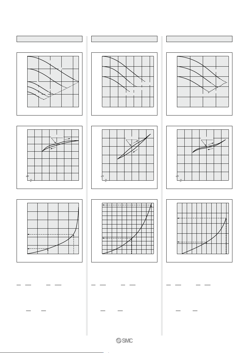
VBA20A, 22A
VBA20A, 22A
Flow-rate Characteristics
Charge Characteristics
Pressure
Characteristics
Inlet pressure: 0.7 MPa
Outlet pressure: 1.0 MPa
Flow rate: 20 L/min (ANR)
Set point
VBA40A, 42A
VBA40A, 42A
P1 = 0.5 MPa
P1 = 0.4 MPa
P1 = 0.3 MPa
Flow-rate Characteristics
Charge Characteristics
Pressure
Characteristics
Inlet pressure: 0.7 MPa
Outlet pressure: 1.0 MPa
Flow rate: 20 L/min (ANR)
Set point
VBA10A
VBA10A
Flow-rate Characteristics
Pressure
Characteristics
Charge Characteristics
Inlet pressure: 0.7 MPa
Outlet pressure: 1.0 MPa
Flow rate: 20 L/min (ANR)
P
1
= 1.0 MPa
P
1
= 0.75 MPa
P
1
= 0.5 MPa
P
1
= 0.4 MPa
P
1
= 0.3 MPa
P1 = P2
Set point
(Representative
value)
(Representative
value)
(Representative
value)
The time required to charge pressure in the
tank from 0.7 MPa to 0.95 MPa at 0.5 MPa
supply pressure:
With the pressure increase ratio from 1.4 to 1.9,
the charge time of 23 – 6 = 17 sec. (t) is given
by the graph. Then, the charge time (T) for a
10
L
tank:
P
2
P1
0.7
0.5
= = 1.4 = 1.9 = 1.6 = 2.0
P
2
P1
0.95
0.5
=
T = t x = 17 x = 17 (s).
V
10
10
10
The time required to charge pressure in the
tank from 0.8 MPa to 1.0 MPa at 0.5 MPa
supply pressure:
With the pressure increase ratio from 1.6 to 2.0,
the charge time of 11.5 – 3.8 = 7.7 sec. (t) is
given by the graph. Then, the charge time (T)
for a 100
L
tank:
P
2
P1
0.8
0.5
=
P
2
P1
1.0
0.5
=
T = t x = 7.7 x = 77 (s).
V
10
100
10
The time required to charge pressure in the
tank from 0.8 MPa to 1.0 MPa at 0.5 MPa
supply pressure:
With the pressure increase ratio from 1.6 to 2.0,
the charge time of 3.5 – 1.1 = 2.4 sec. (t) is given
by the graph. Then, the charge time (T) for a
100 L tank:
P2
P1
0.8
0.5
= = 1.6 = 2.0
P
2
P1
1.0
0.5
=
T = t x = 2.4 x = 24 (s).
V
10
100
10
Series VBA
926
A
1.6
1.4
1.2
1
0.8
0.6
0.4
0.2
Outlet pressure (MPa)
0 500 1000 1500 2000 2500 3000
Outlet air flow rate (L/min (ANR))
1.08
1.06
1.04
1.02
1.0
0.98
0.96
0.94
Outlet pressure (MPa)
0 0.4 0.5 0.6 0.7 0.8 0.9 1
Inlet pressure (MPa)
0.1
0.08
0.06
0.04
0.02
Max. pulsation range (MPa)
0 1 2 3 4 5
Capacity (L)
0.1
0.08
0.06
0.04
0.02
Max. pulsation range (MPa)
0 10 20 30 4038
Capacity (L)
5
4
3
2
1
0
Charge time per 10 L t (s)
1.0 1.1 1.2 1.3 1.4 1.5 1.6 1.7 1.8 1.9 2.0
Pressure increase ratio P2/P1
400
300
200
100
0
Charge time per 10 L t (s)
1.0 2.0 3.0 4.0
Pressure increase ratio P2/P1
Outlet pressure (MPa)
0 0.4 0.5 0.6 0.7 0.8 0.9 1
Inlet pressure (MPa)
2
1
Outlet pressure (MPa)
0 100 15050
Outlet air flow rate (L/min (ANR))
2.1
2.05
2.0
1.95
1.9
1.85
1.8
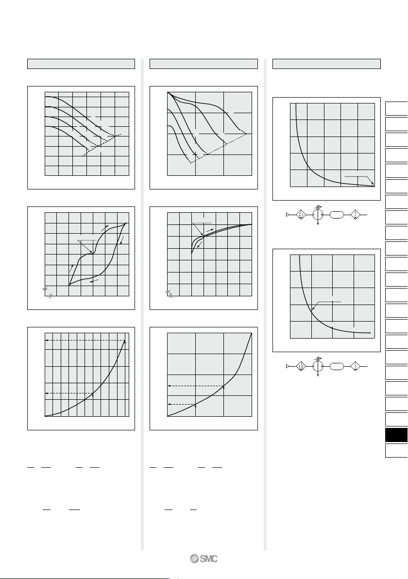
Pulsation/Pulsation is decreased with a tank.
If the outlet capacity is undersized, pulsation may
occur.
Conditions:
Inlet pressure: 0.5 MPa
Outlet set pressure: 1 MPa
Flow rate: Between 0 and max. flow rate
•
Performance of air tank
• Alleviates the pulsation generated on the
outlet side.
• When air consumption exceeds air supply
during intermittent operation, required air
will be accumulated in the tank for use.
This does not apply for continuous
operation.
Flow-rate Characteristics
Charge Characteristics
Pressure
Characteristics
P
1
= 0.8 MPa
P
1
= 0.7 MPa
P
1
= 0.6 MPa
P
1
= 0.5 MPa
P1 = P2
VBAT05A
VBA43A
VBA43A
VBAT05A
VBAT10A, 20A, 38A
VBAT10A
VBAT20A
VBAT38A
VBA11A
VBA11A
Flow-rate Characteristics
Charge Characteristics
Pressure
Characteristics
Set point
Set point
P
1
= 0.4 MPa
P
1
= 0.5 MPa
P
1
= 0.75 MPa
P
1
= 1.0 MPa
P1 = P2
P
1
= 0.3 MPa
Inlet pressure: 0.6 MPa
Outlet pressure: 2.0 MPa
Flow rate: 10 L/min (ANR)
Inlet pressure: 0.7 MPa
Outlet pressure: 1.0 MPa
Flow rate: 20 L/min (ANR)
The time required to charge pressure in the
tank from 0.8 MPa to 1.0 MPa at 0.5 MPa
supply pressure:
With the pressure increase ratio from 1.6 to 2.0,
the charge time of 4.5 – 1.3 = 3.2 sec. (t) is
given by the graph. Then, the charge time (T)
for a 100 L tank:
P
2
P1
0.8
0.5
= = 1.6 = 2.0
P
2
P1
1.0
0.5
=
T = t x = 3.2 x = 32 (s).
V
10
100
10
= 2.0 = 3.0
T = t x = 89 x = 89 (s).
V
10
10
10
The time required to charge pressure in the
tank from 1.0 MPa to 1.5 MPa at 0.5 MPa
supply pressure:
With the pressure increase ratio from 2.0 to 3.0,
the charge time of 147 – 58 = 89 sec. (t) is
given by the graph. Then, the charge time (T)
for a 10 L tank:
P
2
P1
1.0
0.5
=
P
2
P1
1.5
0.5
=
Booster Regulator Series VBA
(Representative
value)
(Representative
value)
VBA2A
VBA4A
VBAT
VBA1
A
VBAT
927
ARJ
AR425
to 935
ARX
AMR
ARM
ARP
IR
IRV
VEX
SRH
SRP
SRF
VCHR
ITV
IC
ITVX
PVQ
VEF
VEP
VER
VEA
VY1
VBA
VBAT
AP100
VBA
VBAT
A