5-p0921-0943-vba_en.pdf - 第7页
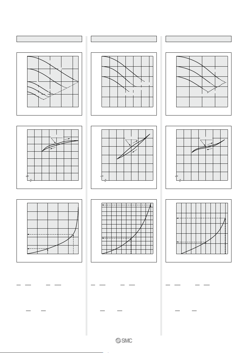
1.6 1.4 1.2 1 0.8 0.6 0.4 0.2 Outlet pressure (MPa) 0 500 1000 1500 2000 2500 3000 Outlet air flow rate (L/min (ANR)) 1.08 1.06 1.04 1.02 1.0 0.98 0.96 0.94 Outlet pressure (MPa) 0 0.4 0.5 0.6 0.7 0.8 0.9 1 Inlet pressur…
12
11
10
9
8
7
6
5
4
3
2
1
0
Charge time per 10 L t (s)
1.0 1.1 1.2 1.3 1.4 1.5 1.6 1.7 1.8 1.9 2.0
Pressure increase ratio P2/P1
1.0
0.8
0.6
0.4
0.2
Outlet pressure (MPa)
0 200 400 600 800 1000 1200
Outlet air flow rate (L/min (ANR))
1.04
1.02
1.0
0.98
0.96
0.94
Outlet pressure (MPa)
0 0.4 0.5 0.6 0.7 0.8 0.9 1
Inlet pressure (MPa)
1.0
0.8
0.6
0.4
0.2
Outlet pressure (MPa)
0 500 1000 1500 2000
Outlet air flow rate (L/min (ANR))
1.04
1.02
1.0
0.98
0.96
0.94
Outlet pressure (MPa)
0 0.4 0.5 0.6 0.7 0.8 0.9 1
Inlet pressure (MPa)
5
4
3
2
1
0
Charge time per 10 L t (s)
1.0 1.1 1.2 1.3 1.4 1.5 1.6 1.7 1.8 1.9 2.0
Pressure increase ratio P2/P1
60
50
40
30
20
10
0
Charge time per 10 L t (s)
1.0 1.2 1.4 1.6 1.8 2.0
Pressure increase ratio P2/P1
2
1.5
1
0.5
Outlet pressure (MPa)
0 100 200 300 400
Outlet air flow rate (L/min (ANR))
1.1
1.05
1.0
0.95
0.9
0.85
0.8
Outlet pressure (MPa)
0 0.50.4 0.6 0.7 0.8 0.9 1
Inlet pressure (MPa)
P1 = 0.5 MPa
P1 = 0.4 MPa
P1 = 0.3 MPa
VBA20A, 22A
VBA20A, 22A
Flow-rate Characteristics
Charge Characteristics
Pressure
Characteristics
Inlet pressure: 0.7 MPa
Outlet pressure: 1.0 MPa
Flow rate: 20 L/min (ANR)
Set point
VBA40A, 42A
VBA40A, 42A
P1 = 0.5 MPa
P1 = 0.4 MPa
P1 = 0.3 MPa
Flow-rate Characteristics
Charge Characteristics
Pressure
Characteristics
Inlet pressure: 0.7 MPa
Outlet pressure: 1.0 MPa
Flow rate: 20 L/min (ANR)
Set point
VBA10A
VBA10A
Flow-rate Characteristics
Pressure
Characteristics
Charge Characteristics
Inlet pressure: 0.7 MPa
Outlet pressure: 1.0 MPa
Flow rate: 20 L/min (ANR)
P
1
= 1.0 MPa
P
1
= 0.75 MPa
P
1
= 0.5 MPa
P
1
= 0.4 MPa
P
1
= 0.3 MPa
P1 = P2
Set point
(Representative
value)
(Representative
value)
(Representative
value)
The time required to charge pressure in the
tank from 0.7 MPa to 0.95 MPa at 0.5 MPa
supply pressure:
With the pressure increase ratio from 1.4 to 1.9,
the charge time of 23 – 6 = 17 sec. (t) is given
by the graph. Then, the charge time (T) for a
10
L
tank:
P
2
P1
0.7
0.5
= = 1.4 = 1.9 = 1.6 = 2.0
P
2
P1
0.95
0.5
=
T = t x = 17 x = 17 (s).
V
10
10
10
The time required to charge pressure in the
tank from 0.8 MPa to 1.0 MPa at 0.5 MPa
supply pressure:
With the pressure increase ratio from 1.6 to 2.0,
the charge time of 11.5 – 3.8 = 7.7 sec. (t) is
given by the graph. Then, the charge time (T)
for a 100
L
tank:
P
2
P1
0.8
0.5
=
P
2
P1
1.0
0.5
=
T = t x = 7.7 x = 77 (s).
V
10
100
10
The time required to charge pressure in the
tank from 0.8 MPa to 1.0 MPa at 0.5 MPa
supply pressure:
With the pressure increase ratio from 1.6 to 2.0,
the charge time of 3.5 – 1.1 = 2.4 sec. (t) is given
by the graph. Then, the charge time (T) for a
100 L tank:
P2
P1
0.8
0.5
= = 1.6 = 2.0
P
2
P1
1.0
0.5
=
T = t x = 2.4 x = 24 (s).
V
10
100
10
Series VBA
926
A
1.6
1.4
1.2
1
0.8
0.6
0.4
0.2
Outlet pressure (MPa)
0 500 1000 1500 2000 2500 3000
Outlet air flow rate (L/min (ANR))
1.08
1.06
1.04
1.02
1.0
0.98
0.96
0.94
Outlet pressure (MPa)
0 0.4 0.5 0.6 0.7 0.8 0.9 1
Inlet pressure (MPa)
0.1
0.08
0.06
0.04
0.02
Max. pulsation range (MPa)
0 1 2 3 4 5
Capacity (L)
0.1
0.08
0.06
0.04
0.02
Max. pulsation range (MPa)
0 10 20 30 4038
Capacity (L)
5
4
3
2
1
0
Charge time per 10 L t (s)
1.0 1.1 1.2 1.3 1.4 1.5 1.6 1.7 1.8 1.9 2.0
Pressure increase ratio P2/P1
400
300
200
100
0
Charge time per 10 L t (s)
1.0 2.0 3.0 4.0
Pressure increase ratio P2/P1
Outlet pressure (MPa)
0 0.4 0.5 0.6 0.7 0.8 0.9 1
Inlet pressure (MPa)
2
1
Outlet pressure (MPa)
0 100 15050
Outlet air flow rate (L/min (ANR))
2.1
2.05
2.0
1.95
1.9
1.85
1.8
Pulsation/Pulsation is decreased with a tank.
If the outlet capacity is undersized, pulsation may
occur.
Conditions:
Inlet pressure: 0.5 MPa
Outlet set pressure: 1 MPa
Flow rate: Between 0 and max. flow rate
•
Performance of air tank
• Alleviates the pulsation generated on the
outlet side.
• When air consumption exceeds air supply
during intermittent operation, required air
will be accumulated in the tank for use.
This does not apply for continuous
operation.
Flow-rate Characteristics
Charge Characteristics
Pressure
Characteristics
P
1
= 0.8 MPa
P
1
= 0.7 MPa
P
1
= 0.6 MPa
P
1
= 0.5 MPa
P1 = P2
VBAT05A
VBA43A
VBA43A
VBAT05A
VBAT10A, 20A, 38A
VBAT10A
VBAT20A
VBAT38A
VBA11A
VBA11A
Flow-rate Characteristics
Charge Characteristics
Pressure
Characteristics
Set point
Set point
P
1
= 0.4 MPa
P
1
= 0.5 MPa
P
1
= 0.75 MPa
P
1
= 1.0 MPa
P1 = P2
P
1
= 0.3 MPa
Inlet pressure: 0.6 MPa
Outlet pressure: 2.0 MPa
Flow rate: 10 L/min (ANR)
Inlet pressure: 0.7 MPa
Outlet pressure: 1.0 MPa
Flow rate: 20 L/min (ANR)
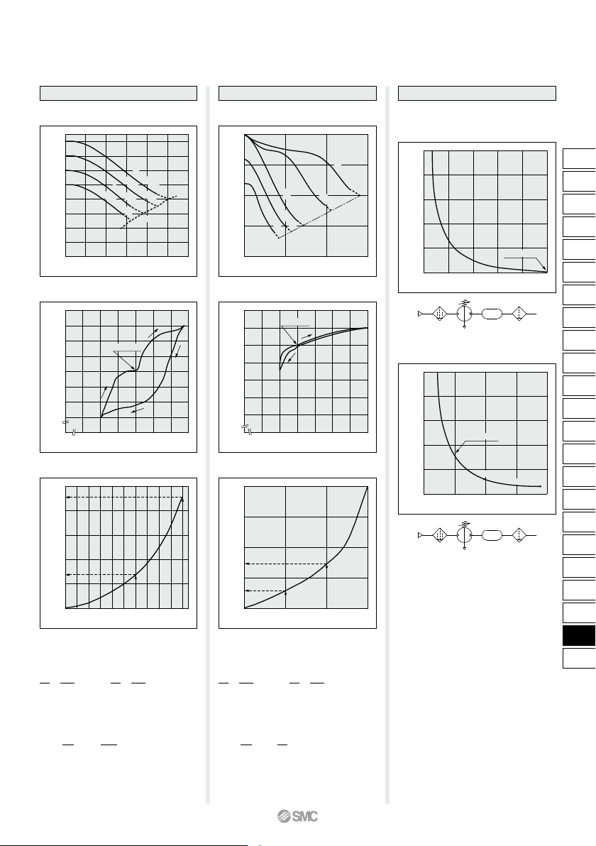
The time required to charge pressure in the
tank from 0.8 MPa to 1.0 MPa at 0.5 MPa
supply pressure:
With the pressure increase ratio from 1.6 to 2.0,
the charge time of 4.5 – 1.3 = 3.2 sec. (t) is
given by the graph. Then, the charge time (T)
for a 100 L tank:
P
2
P1
0.8
0.5
= = 1.6 = 2.0
P
2
P1
1.0
0.5
=
T = t x = 3.2 x = 32 (s).
V
10
100
10
= 2.0 = 3.0
T = t x = 89 x = 89 (s).
V
10
10
10
The time required to charge pressure in the
tank from 1.0 MPa to 1.5 MPa at 0.5 MPa
supply pressure:
With the pressure increase ratio from 2.0 to 3.0,
the charge time of 147 – 58 = 89 sec. (t) is
given by the graph. Then, the charge time (T)
for a 10 L tank:
P
2
P1
1.0
0.5
=
P
2
P1
1.5
0.5
=
Booster Regulator Series VBA
(Representative
value)
(Representative
value)
VBA2A
VBA4A
VBAT
VBA1
A
VBAT
927
ARJ
AR425
to 935
ARX
AMR
ARM
ARP
IR
IRV
VEX
SRH
SRP
SRF
VCHR
ITV
IC
ITVX
PVQ
VEF
VEP
VER
VEA
VY1
VBA
VBAT
AP100
VBA
VBAT
A
Tc Ts
Pressure
Stroke
Upper limit of pressure inside the tank P3
Inlet pressure P1
Time
Necessary supply
pressure to cylinder P
2
Sizing
( )
END
START
NO
NO
NO
YES
YES YES YES
YES
When running continuously for longer periods of time, confirm the life expectancy.
When the life expectancy is shorter than required, select a larger sized booster regulator.
Select the tank
from table below.
Judgement of
flow rate
Extend
stop time Ts
up to charge time
T or more.
Avoid
pulsation.
(Max. 0.05
MPa)
Judgement
of charge time
T ≤ T s
Provide requisite
conditions for
selection.
Calculate required
air flow rate Q.
Select booster regulator
size from flow-rate
characteristics table.
Obtain the tank
capacity V.
Select the tank
capacity over V.
Calculate time T from
charge characteristics
table.
Increase number of
booster regulators (Z)
to decrease T.
Tank model
VBAT05
VBAT10
VBAT20
VBAT38
VBA1A
VBA1A
—
—
—
VBA2A
VBA2A
VBA2A
—
—
VBA4A
VBA4A
Applicable combination modelInternal capacity
5 L
10 L
20 L
38 L
•
Use the VBA11A (pressure increase ratio 4) with pressure
increase ratio 2 to 4. Usage of pressure increase ratio below 2
is preferred for the VBA10A (pressure increase ratio 2).
A stable operation and increased life expectancy will result.
•
Inlet supply pressure volume is {approximately twice (pressure
increase ratio 2), approx. 4 times (pressure increase ratio 4)}
the volume of the outlet side. Booster regulator requires the
inlet side volume which is the sum of the flow volume running
into the outlet side and the volume exhausted from E port (for
driving), because air is the power source.
Sizing can be achieved with the SMC Pneumatic System Energy Saving Program Ver. 3.1
which can be downloaded from the SMC website: http://www.smcworld.com
Caution
Lower limit of pressure inside the tank P2
100
100
200
1
0.5
30
0.5
0.8
Example
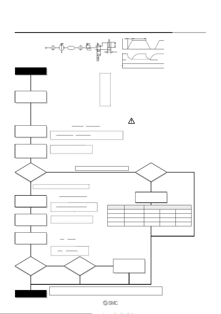
Necessary conditions:
D [mm]: Cylinder bore size
L [mm]: Cylinder stroke
W [mm/s]: Cylinder operating speed
C [pc.]: Number of cylinders
Tc [s]: Cylinder operating time
Ts [s]: Cylinder stop time
P
1 [MPa]: Inlet pressure
P
2 [MPa]
Note 1)
: Necessary supply
pressure to cylinder
Note 1) P2 is the necessary supply pressure to a cylinder, and set the pressure below the lower limit of pressure inside the tank
with a regulator. Adjust the pressure taking the maximum operating pressure of equipment in use into consideration.
Note 2) P
3 is the output pressure of the booster regulator, which is also the upper limit of charge pressure to the tank.
Other conditions:
Q [L/min (ANR)]: Required air flow rate
Qb [L/min (ANR)]: Outlet air flow rate of booster regulator
Tc [s]: Cylinder operating time
K: Cylinder double-acting: 2, single-acting: 1
P
3 [MPa]
Note 2)
: Tank charge pressure
T
1 [s]: Time to charge (Time to charge to P2)
T
2 [s]: Time to charge (Time to charge to P3)
T
[s]: Time to charge (Time to charge from P2 to P3)
Z: Number of booster regulators
Q [L/min (ANR)] =
π x D
2
x W
x
(P
2
+ 0.101)
x 60 x C
4 x 10
6
0.101
Q =
π x 100
2
x 200 (0.8 + 0.101)
x 60 x 1 = 841 [L/min (ANR)]x
4 x 10
6
0.101
Refer to “Flow-rate Characteristics” on pages 926 and 927.
VBA2A: Qb = 600 [L/min (ANR)]
VBA4A: Qb = 1050 [L/min (ANR)]
NO: Need no tank
The VBA4A can supply necessary pressure.
The VBA2A cannot obtain necessary pressure.
(P
3 – P2) x 9.9
V [L] =
(Q – Qb/2) x (Tc x K/60)
V = = 4.6 [L]
(1.0 – 0.8) x 9.9
Select the VBAT10, which can be
directly connected to the
VBA2A.
(841 – 600/2) x (0.5 x 2/60)
Refer to “Charge Characteristics” on pages 926 and 927.
T = ( ) x = 3.5 [s]
T [s] = ( ) x
T
2 – T1V
10
4.6
10
Z
11.5 – 3.8
1
Series VBA
øD
L
P2
P3P1
928