5-p0921-0943-vba_en.pdf - 第12页
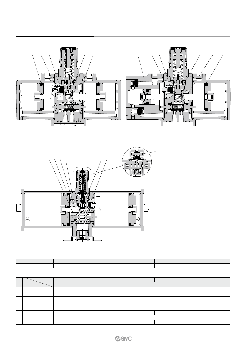
w q r e w t r e u q t Construction/Replacement Parts VBA10A VBA11A q w r y q t e Air-operated type VBA22A, 42A VBA20A, 22A, VBA40A, 42A, 43A Replacement Parts/Kit No. The kit includes the parts from q to u and a grease p…
Handling
1
0.9
0.8
0.7
0.6
0.5
0.5
0.4
0.4
0.3
0.3
0.2
0.2
Pilot pressure MPa
0.1
0.1
0
Outlet pressure MPa (Q = 0)
SMC
HighLow
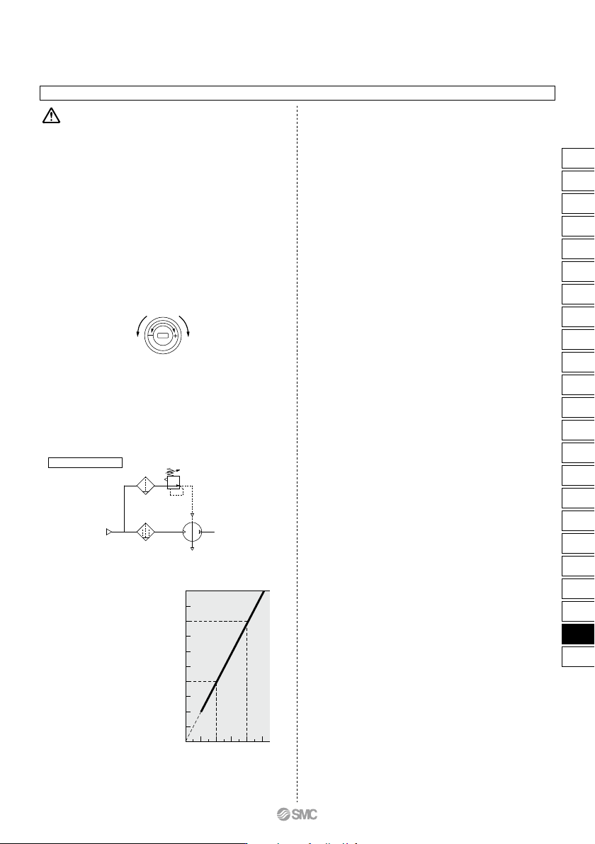
1. Setting the pressure on the handle-operated type
• If air is supplied to the product in the shipped state, the air
will be released.
Set the pressure by quickly pulling up on the governor
handle, releasing the lock, and rotating the handle in the
direction of the arrow (+).
• There is an upper and lower limit for the handle rotation. If
over-rotating the handle even after reaching to the limit, the
internal parts may be damaged. If the handle suddenly feels
heavy while being turned, stop turning the handle.
• Once the setting is completed, push the handle down and
lock it.
• To decrease the outlet pressure, after the pressure has
been set, rotate the handle in the direction of the arrow (–).
The residual air will be released from the area of the
handle, due to the relief construction of the governor.
• To reset the pressure, first reduce the pressure so that it is
lower than the desired pressure; then, set it to the desired
pressure.
Caution
2. Setting the pressure on the air-operated type
(VBA22A, 42A)
• Connect the outlet pipe of the pilot regulator for the remote
control to the pilot port (P). (Refer to the diagram below.)
• Refer to the graph below for the relationship between the
pilot pressure and outlet pressure.
• The AR20 and AW20 are recommended for the pilot regula-
tor.
Pilot regulator
• The outlet pressure is twice the pilot pressure.
• When the inlet pressure is 0.4 MPa:
Pilot pressure
0.2 MPa to 0.4 MPa
Outlet pressure
0.4 MPa to 0.8 MPa
3. Draining
• If this product is used with a large amount of drainage
accumulated in the filter, mist separator or tank, the
drainage could flow out, leading to equipment malfunction.
Therefore, drain the system once a day. If it is equipped
with an auto drain, check its operation once a day.
4. Exhaust
• Exhausting time from E port may be longer for a booster
regulator which is set to switch in longer hour intervals. This
is not an abnormal phenomenon.
5. Maintenance
• Life expectancy varies depending on the quality of air and
the operating conditions. Signs that the unit is reaching the
end of its service life include the following:
•
Constant bleed from under the handle.
•
Air exhaust noise can be heard from the booster regulator
at 10 to 20 second intervals even when there is no air
consumption on the outlet side.
Conduct maintenance earlier than scheduled in such cases.
• When maintenance is required, confirm the model and serial
number of the booster regulator, and please contact SMC
for maintenance kit.
• Conduct maintenance according to the specified mainte-
nance procedure by individuals possessing enough knowl-
edge and experiences in maintaining pneumatic equipment.
• The list of replacement parts and kit number are shown on
page 932, and the figure shows the position of the parts.
Booster Regulator Series VBA
P
E
IN
OUT
931
ARJ
AR425
to 935
ARX
AMR
ARM
ARP
IR
IRV
VEX
SRH
SRP
SRF
VCHR
ITV
IC
ITVX
PVQ
VEF
VEP
VER
VEA
VY1
VBA
VBAT
AP100
VBA
VBAT
w
q r e w t
r e
u
q
t
Construction/Replacement Parts
VBA10A VBA11A
q
wryqt e
Air-operated type
VBA22A, 42A
VBA20A, 22A,
VBA40A, 42A, 43A
Replacement Parts/Kit No.
The kit includes the parts from q to u and a grease pack.
Model
No.
1
2
3
4
5
6
7
—
Piston seal
Governor assembly
Check valve
Gasket
Rod seal
Mounting screw
Cover C assembly
Grease pack
Description
Place an order with the following applicable kit number.
Model
Kit no.
VBA43A VBA11AVBA42AVBA22AVBA40AVBA20AVBA10A
KT-VBA10A-1 KT-VBA20A-1 KT-VBA40A-1 KT-VBA22A-1 KT-VBA42A-1 KT-VBA43A-1 KT-VBA11A-20
VBA43A VBA11AVBA42AVBA22AVBA40AVBA20AVBA10A
Quantity
2
2
1
8
—
8 12
1
—
2 1 2
1
—
1
1
12
1 each large and small
2
2 large 1 small 2
∗ The grease pack has 10 g of grease.
∗ Make sure to refer to the procedure for maintenance.
4
Series VBA
932
IN side gauge port
1/8
300
39
OUT side gauge port
1/8
Pressure gauge (Option)
3.2
73
53
IN side gauge port
1/8
OUT side gauge port
1/8
Pressure gauge (Option)
3.2
404
40
116
96
OUT port
1/4
IN port
1/4
4 x ø5.5
EXH port
1/4
Silencer
(Option)
(When silencer installed: 107)
(When high-noise reduction
silencer installed: 126)
287
2327
60
70
22
113
(When silencer installed: 107)
(When high-noise reduction
silencer installed: 126)
Silencer
(Option)
4 x ø5.5
IN port
1/4
OUT port
1/4
EXH port
1/4
287
2327
60
70
22
113
OUT port
3/8
IN port
3/8
Silencer (Option)
4 x ø12
EXH port
3/8
15
(When silencer installed: 153.5)
(When high-noise reduction
silencer installed: 179)
28
176
4346
21
98
118
24
OUT port
1/2
IN port
1/2
Silencer (Option)
EXH port
1/2
8
4 x ø12
(When silencer installed: 200)
(When high-noise reduction
silencer installed: 230)
43
22
62.8 62
215
32
150
130
IN port
1/4
OUT port
1/4
Elbow silencer (Option)
EXH port
1/4
4 x ø5.5
113
2327
(97)
70
60
22
287
IN port
1/4
OUT port
1/4
Elbow silencer (Option)
EXH port
1/4
4 x ø5.5
113
2327
(97)
70
60
22
287
Pressure gauge (Option)
8.5
150
60
50
40
IN side
gauge port
Rc 1/8
OUT side
gauge port
Rc 1/8
Pressure gauge (Option)
33 30
8.5
50
40
150
IN side
gauge port
Rc 1/8
OUT side
gauge port
Rc 1/8
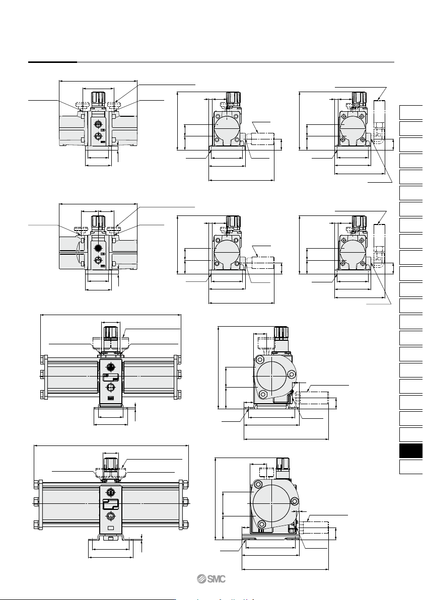
Dimensions
VBA10A-02
VBA11A-02
VBA20A-03
VBA40A-04
With elbow silencer (Option)
With elbow silencer (Option)
Booster Regulator Series VBA
933
ARJ
AR425
to 935
ARX
AMR
ARM
ARP
IR
IRV
VEX
SRH
SRP
SRF
VCHR
ITV
IC
ITVX
PVQ
VEF
VEP
VER
VEA
VY1
VBA
VBAT
AP100
VBA
VBAT