00196497-07_SM_SXDX12_en.pdf - 第256页
Settings Electrical and Control Settings 4.3.3 CAN I/O Module 256 Service Manual SIPLACE SX1/SX2/DX1/DX2 FS02 4.3.3 4 . 3 . 3 C A N I / O M o d u le CAN I/O Module Up to machine nos.: Mxxx For I/O module [03052315-xx]
Settings
4.3.1 Fuses Electrical and Control Settings
Service Manual SIPLACE SX1/SX2/DX1/DX2 FS02 255
4.3
4.3 Electrical and Control Settings
Electrical and Control Settings
4.3.1
4.3.1 Fuses
Fuses
For more information about this, read section "5.1.4 Fuse Connection Board" [ ➙ 309].
4.3.2
4.3.2 Setting the Voltage on the AC/DC Converters
Setting the Voltage on the AC/DC Converters
Parts, Equipment and Tools
▪ Voltage measuring device
Overview
The AC/DC converters are located at the following positions:
▪ PS1: in sector 3 on the power supply switching unit (25 V)
AC/DC converter DC24V/20A 3 phase [03055232-xx]
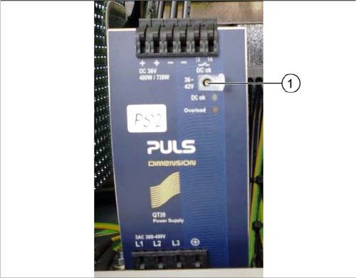
▪ PS2: in sector 3 on the power supply switching unit (42 V)
AC/DC converter DC36-42V/13.3A 3 phase [03076588-xx]
▪ PS3: in sector 2 (26,8 V)
AC/DC converter DC24V/20A 3 phase [03055232-xx]
Setting
Setting the AC/DC converter
► Open the protective cap on the setting screw (1).
► Rotate with a slotted screwdriver until the AC/DC
converter provides the correct voltage.
Use a suitable voltage measuring device to check the
voltage between the + and – terminals.
Settings
Electrical and Control Settings 4.3.3 CAN I/O Module
256 Service Manual SIPLACE SX1/SX2/DX1/DX2 FS02
4.3.3
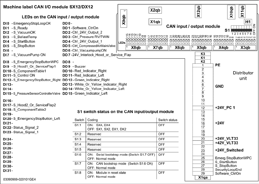
4.3.3 CAN I/O Module
CAN I/O Module
Up to machine nos.: Mxxx
For I/O module [03052315-xx]
Settings
4.3.3 CAN I/O Module Electrical and Control Settings
Service Manual SIPLACE SX1/SX2/DX1/DX2 FS02 257
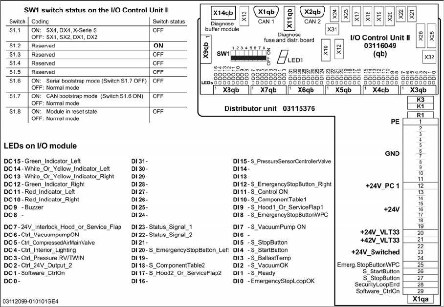
From machine nos.: N001
For I/O module [03116049-xx]