00196497-07_SM_SXDX12_en.pdf - 第289页
Settings 4.6.7 Board Clamping Conveyor Settings Service Manual SIPLACE SX1/SX2/DX1/DX2 FS02 289 4.6.7 4 . 6 . 7 B o a r d C la m p in g Board Clamping 4.6.7.1 4 . 6 . 7 . 1 S e t t in g t h e B o a r d C la m p in g ( A …
Settings
Conveyor Settings 4.6.6 Conveyor Width Calibration
288 Service Manual SIPLACE SX1/SX2/DX1/DX2 FS02
4.6.6
4.6.6 Conveyor Width Calibration
Conveyor Width Calibration
► Open the Service view.
► Click on the Single calibration button.
► Click on the Conveyor Lane 1 or Conveyor Lane 2 button.
► Click on the Calibrate conveyor width... button. The dialog box Calibrate conveyor width will open.
► Place a 100 mm wide board into the selected conveyor lane and click on the Increase (small step)
or Decrease (small step), buttons to set the conveyor width stepwise to the board width.
► Click on the Cancel... button, to close the dialog box.
► Open the Manual operations > Subsystems view.
► Click on the Conveyor Lane 1 or Conveyor Lane 2 button, to switch over to the Manual operations >
Subsystems > Conveyor Lane x > Functions view.
► Test whether the board can be transported smoothly through the machine, without problems.
► Press the following buttons one after the other: Input section, placement section, intermediate sec-
tion, placement section and output section.
► Click on the icon, to return to the Service > Manual operations > Conveyor Lane x view.
► Click on the Calibrate conveyor width... button. The dialog box Calibrate conveyor width will open.
► Click on the OK button. The dialog box will close and the conveyor width will be calibrated to the
board width.
► Click on the Save machine data for conveyor
button, to save the data generated during calibration
in the machine data.
NOTICE
Calibration
► Use a 100 mm wide board to calibrate the conveyor width.
► Switch the dual conveyor between "fixed right" and "fixed left". This ensures that all convey-
or sides are calibrated.
Settings
4.6.7 Board Clamping Conveyor Settings
Service Manual SIPLACE SX1/SX2/DX1/DX2 FS02 289
4.6.7
4.6.7 Board Clamping
Board Clamping
4.6.7.1
4.6.7.1 Setting the Board Clamping (Actuator)
Setting the Board Clamping (Actuator)
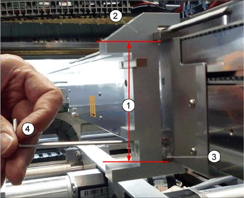
If the conveyor control issues the error Clamping error conveyor, you need to check the distance from
the lifting table actuator to the upper edge of the conveyor belt.
Parts, equipment and tools
▪ Setting gauge for actuator [03049740-xx]
▪ Terminal strip [03076699-xx]
Setting
► Fit the terminal strip onto the long side of the setting gauge.
► Loosen the screws fastening the actuator.
► Attach the setting gauge to the conveyor side, as shown in the diagram.
► Tighten the screws fastening the actuator. This sets the distance to 94.0 mm.
► Repeat this setting at all actuators.
1. Distance of 94.0 mm from the lower edge of the actu-
ator to the upper edge of the conveyor toothed belt
2. Setting gauge
3. Actuator.
4. Loosen and tighten the screws fastening the actuator
through the hole provided in the gauge.
Settings
Conveyor Settings 4.6.8 Lifting Table
290 Service Manual SIPLACE SX1/SX2/DX1/DX2 FS02
4.6.8
4.6.8 Lifting Table
Lifting Table
4.6.8.1
4.6.8.1 Setting the Parallelism and Height of the Lifting Table Plate
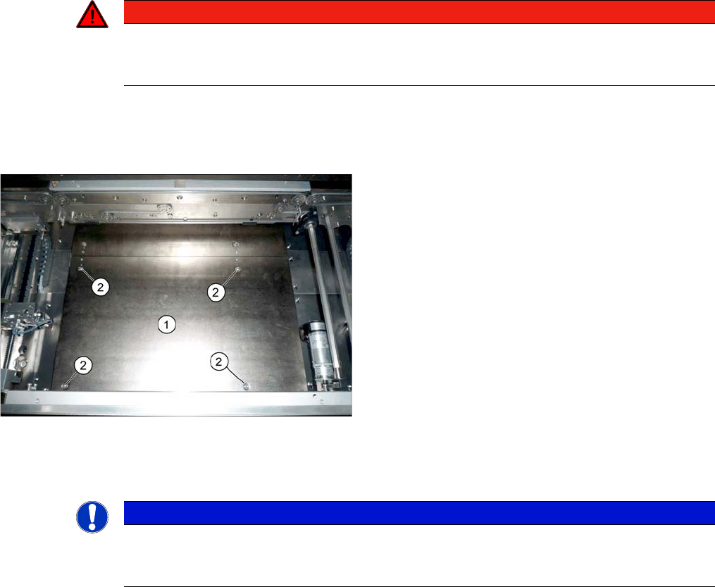
Setting the Parallelism and Height of the Lifting Table Plate
Overview
Setting
► Use the software to move the conveyor sides to maximum width. (See "3.6.1 Loosening the Convey-
or Side Clamps" [ ➙ 143])
► Loosen the screws fastening the lifting table plate but do not remove the lifting table plate.
► Use the software to clamp the lifting table (without board).
► Underneath the fastening screws, there are setting screws (socket-head 5). Use these setting
screws to set the lifting table plate so that it has no play between it and the clamping edge.
► Check all four corners of the lifting table for any play.
► Check the setting by clamping a board into place. Check all corners to see whether there is any play.
► Calibrate the zero position of the lifting table motor.
See also
4.6.5 Calibrating the Motors in the Conveyor [ ➙ 287]
1.2 Preparatory Work... [ ➙ 13]
DANGER
Press the EMERGENCY STOP!
Before performing adjustment work you must ensure that the lifting table has been secured
against movement!
Lifting table plate (example of SX1/SX2 V2 shown)
1. Lifting table plate
2. Fastening screws for lifting table plate
NOTICE
Single, dual conveyor
The setting is shown in the diagram using the example of a lifting table unit for the dual conveyor
(DC). Setting the single conveyor (SC) follows the same procedure.